Interlocking between manual switches

Thread Starter

sab201

Joined Nov 18, 2023
146
Good Day,

I have searched about this on google and found no solution. I am looking for advice in this circuit. I have 7 PWM generator circuits and I wish to switch them ON and OFF manually as and when I wish. Switches S1 to S7 are manual. But incase more than one switch is pushed on accidentally then I want no supply going to the circuits 1 to 7 so that there is only one PWM output at a time and when there is more than one it is avoided.
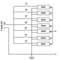
20240627_121910_0000.jpg
Is it possible to provide this interlock in the circuit.

Thanks.
 

Thread Starter

sab201

Joined Nov 18, 2023
146
Can you use a rotary switch for selection and a power supply toggle for on,/off?
Great! That's a good solution. A rotary switch for selection. I didn't think of that and I was thinking of so many other ways to provide interlock. This is the simplest solution.

Thanks a lot, nsaspook.
 
To ensure only one PWM generator circuit receives power at a time, you can implement a circuit with interlocking switches. Here's a possible solution using diodes and DPDT switches:
  • Replace the existing single-pole double-throw (SPDT) switches (S1-S7) with DPDT switches.
  • Connect the common terminal of each DPDT switch to the 5V DC supply.
  • Connect one output of each DPDT switch to its corresponding PWM circuit (Circuit 1-7).
  • Connect the other output of each DPDT switch together.
  • Place a diode in series with each of these interconnected outputs, with the anode facing away from the switches.
With this setup, when a DPDT switch is thrown, it supplies power to its corresponding circuit through one output, while the other output is blocked by the diode. The diode prevents current from flowing back into the common connection, stopping other circuits from turning on.
 

Thread Starter

sab201

Joined Nov 18, 2023
146
With this setup, when a DPDT switch is thrown, it supplies power to its corresponding circuit through one output, while the other output is blocked by the diode. The diode prevents current from flowing back into the common connection, stopping other circuits from turning on.
Thanks, felanhardware. I will try it out. Using ON/OFF individual switches with interlock the design part could be taking more effort but the ease of use is simplified than using a rotary switch.
 
Weren't you told in the other thread connecting all of the 555 outputs together like that was a bad idea.

You are still going to have to OR gate those outputs using some kind of method.
 

Thread Starter

sab201

Joined Nov 18, 2023
146
Weren't you told in the other thread connecting all of the 555 outputs together like that was a bad idea.

You are still going to have to OR gate those outputs using some kind of method.
Yes you are right I am planning to put extra manual switches at the outputs to select them after the supply selection of the inputs is made. I dont want to mess with the PWM outputs using gates.

I am also trying to get MCUs like I discussed in other thread but that involves setting up my pc that will take time and budget. Its been a long time I used PCs and my laptop got too old and got screen problems. So I wait and sort that out while I find an easier way to work the hardware out in the meantime.
 

Thread Starter

sab201

Joined Nov 18, 2023
146
Why?
The gates will have no significant effect on the output signal characteristics unless you are driving a low-impedance load.
Thanks for the information. The load is a mosfet switching module. I read on other threads that adding diodes and other components significantly reduces the PWM speed control of motors so I had that doubt and didn't want to mess with that.
 

Thread Starter

sab201

Joined Nov 18, 2023
146
To ensure only one PWM generator circuit receives power at a time, you can implement a circuit with interlocking switches. Here's a possible solution using diodes and DPDT switches.
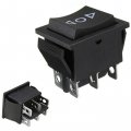
I suppose you are talking about this 6 pin DPDT switch.
1_fa094160-e794-4ddb-b432-7145394b26f6.jpg

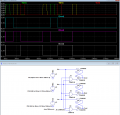
I made the circuit but I am not sure if it would work. Using DPDT switches here is the circuit. (Excuse that messy drawing it was made and corrected using Canva on android phone).
sketch-1719507279792.jpgThe top load side of the DPDT switches shown + and GND are interchanged. Excuse that it was to avoid space...

So when DPDT 1 is thrown down, and incase DPDT 2 is thrown down at the same time I suppose it behaves like a normal circuit and there is no interlock.
 

crutschow

Joined Mar 14, 2008
34,894
I dont wish to use momentary push buttons but this circuit seems to use ON/OFF switch.
It requires momentary switches.
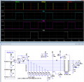
I didn't have a simulation momentary switch so had to use the standard.

If you don't want to use momentary switches, then the radio circuit has no use, since it only works with that (selects the output for the last PB pressed).
 

Thread Starter

sab201

Joined Nov 18, 2023
146
It requires momentary switches.
I didn't have a simulation momentary switch so had to use the standard.

If you don't want to use momentary switches, then the radio circuit has no use, since it only works with that (selects the output for the last PB pressed).
Oh Ok, thanks for your help then I would best go with the rotary switch option for now and selector switches for pwm outputs. Then after I implement MCU that would get much easier.
 
Top