Facebook
 Google
 GitHub
 Linkedin
Hi all ,
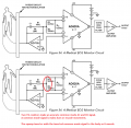
I'm working on INA 111 instrumentation amplifier where I'm input the value of 120 Vp-p and 68kHz frequency and set the gain (as given in datasheet - equation ) to 100 - gain ,
When I'm connecting the input from a Function generator , the value is amplified correctly and output of about 12 Vp-p approx.
But When the Input is connected from the pair of electrodes from the Human body ( which senses the voltage drop ) of 120 Vp-p , the output of INA 111 is not gained properly - output of 2.5 Vp-p with offset of 1V (irregular and improper gain) .
2,3 pin -> connected to Electrode wire terminal from human body OR Function generator for Checking.
6 -> output pin , 5 -> grounded .
Please help to fix this issue , thanks in advance !