Input to transistor turning on when connected to unpowered source.

Thread Starter

peckett

Joined May 9, 2021
18
Hello

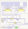
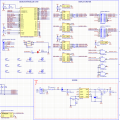
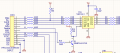
I have to electronic circuit boards, on acts as a controller and the other as a display panel.
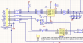
I want to disable the buffer IC on the display panel until the controller is connected and powered.
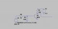
I added a simple transistor switch to the enable pin of the buffer so it is pulled high unless the 3V3 from the controller is connected through a cable in which case the transistor will turn on and enable the buffer.
When I power the display panel and connect the data cable from the display panel to the controller I get about 1.5V on the input of the transistor even though the controller is unpowered and I cannot work out where it is coming from.
I cut the 3V3 track going from my switching regulator to the associated pin on the connector of the controller and the input signal of the transistor went low as expected.
Please can someone help me understand where this mysterious 1.5V signal is coming from? I even tried connecting the transistor input signal to another logic IC and got the same result.
I also tried adding pulldown resistor to input of transistor but still it is getting pulled to 1.5V from somewhere.
 

Attachments

Alec_t

Joined Sep 17, 2013
14,330
Leakage across the connector CON1?
Interference pick-up on the track between CON1 and R18?
Capacitive coupling of the switcher regulator oscillation?

Try putting a decoupling cap (~10nF?) on the transistor gate.
 

Thread Starter

peckett

Joined May 9, 2021
18
Thanks alec_t

I got this response on eevblog from capt bullshot

Guessing:

You've got some lines called xxx_Ret / MISO from the display to the controller. If these are outputs at the display side and inputs at the controller side, and by some chance are at "high" level when the display is powered but not the controller, you get a reverse power flow through these lines.
These lines at "high" level can inject power into the controller circuitry through the usual protection diodes within the ICs used at the controller side. This brings up the VCC of the controller to any value from zero to about nominal VCC - 0.5V. Often the controller doesn't operate correctly or not at all in this state, but puts out undefined voltages at other pins (like your enable pin).

To solve this choose one or more of these hints

- take care all outputs from display to controller are at "low" level if the controller isn't powered. This is always recommended, because such leakage current from "high" outputs to unpowered circuitry can cause all kinds of weird effects
- put a low enough value pull down resistor at the enable input. Might work as a simple workaround.
- use a resistor from base to emitter of this transistor to create a voltage divider that turns on the transistor e.g. above 2V. This is always good practice, otherwise the transistor could be turned on by very small leakage currents or stray voltages.

I think this was the problem and I solved the problem by adding the base to emitter resistor to prevent the transistor switching at 1.5V.
 

Attachments

Alec_t

Joined Sep 17, 2013
14,330
I think this was the problem and I solved the problem by adding the base to emitter resistor to prevent the transistor switching at 1.5V.
Glad you've solved the problem. I didn't mention adding that pull-down resistor because you said in post #1 that you'd already tried that.
 

Thread Starter

peckett

Joined May 9, 2021
18
Ahh so I did I think i did it only looking at it as a pull down resistor and not a voltage divider so would have picked the wrong values. Thank your for your input.
 

Art Mezins

Joined May 26, 2019
11
As the emitter is grounded, that resistor you added is not called a base-to-emitter resistor, but it's a basic "pull down" that drains stray "energy" into the base and aids in faster turn-off. Test this by removing that resistor or prototyping one with the same arrangement as in the original schematic, have a wire into where the control is normally input and touch it with your finger. The stray EM will turn on that transistor, which could also happen in your lab, especially if any EM sources are nearby.

A true base-to-emitter resistor would really be in series with the emitter and ground and act as negative feedback (i.e. the more current entering the base and collector, the more current into that resistor increases its voltage and reduces Vbe, thereby reducing collector current.
 

Thread Starter

peckett

Joined May 9, 2021
18
The aim wasn't to reduce the collector current, it was to stop the stray voltage I was getting from the controller enabling the input buffer on the display panel and causing LED's to be on when they are not suppose to.
When power to the controller is removed halfway through a display pattern on the display panel the LED's need to turn off.
The output of the buffer returning MISO from the display panel remained high and it would cause a voltage to be present on the 3.3V and other connector pins of the unpowered controller which I was using to control the transistor to enable or disable the buffer on the display panel controlling the LEDs.
Because this voltage was always measured at 1.5V I used the attached circuit to only enable the IC buffer when the input is above ~2.8V so the 1.5V stray voltage would no longer turn it on.
 

Attachments

Art Mezins

Joined May 26, 2019
11
I never said this was to reduce collector current, but that's what you can (and do?) get if the external circuit is off and the LCD circuit is powered. There may also be a stray current paths in an off-board circuit's IC when it's powered down but "accidentally" powered by I/O protection diodes on the main board turning on. Sometimes that kind of problem requires inverting the logic sense between boards if you cannot guarantee that both are always on or off simultaneously. It's hard to be conclusive when a full set of applicable schematics are not provided.
 

Thread Starter

peckett

Joined May 9, 2021
18
inverting logic sense between boards? They will usually both be on but it is for a speed limit sign so if for some reason there is a loss of connection then the display needs to be blank. I have attached more of the schematics to this post, was trying to avoid posting the whole thing.
I have attached the original schematics that have the problem along with the modification I have done.
The LED drivers are active low, so there was originally just a pull up resistor on the enable pin that was suppose to disable the led drivers when it is not being driven low by the controller.
That circuit didn't work as the enable was driven low whether the controller was powered or not.
So I modified the board and cut the enable of the buffer IC and tied it to the transistor circuit so I can prevent all the signals from passing through when the buffer IC on the display driver does not receive a solid >2.8V signal.
Please excuse the messiness of the schematic I did not design the display panel and only drew the modifications for demonstration on what I have done.
So P3 from the controller is connected to CON1 of the display panel.

Thanks
 

Attachments

Top