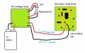
infrared break beam circuit

scubasteve_911

Joined Dec 27, 2007
1,203
Hi ,

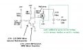
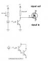
Here's an image that should clear up your confusion. You don't need an inverter for it to work, that was basically used to invert the signal and to give a buffer. The output of the impedance of that circuit was 10K, which was a bit much. That resistor value needed to be adjusted for different photodiodes.

I would use a packaged solution, like the part I originally pointed out. Hook it up as the picture shows. Calculate the values of the current limiting resistor to the LED as instructed, along with the pullup from the transistor. This is probably the simplest solution. The only thing I would add-on, in your case, is a MOSFET as a switch. This will give you more power handling.

http://www.electronics-tutorials.ws/transistor/tran_7.html

Steve

PS- You aren't dense, you're just new. I knew a guy in 4th year university that didn't know how to hook up one of these sensors..
 
Last edited:
scubasteve_911

Joined Dec 27, 2007
1,203
Yeah, that looks good. So, when the transistor gets enough light, the mosfet will shutoff. When it isn't recieving light, the mosfet will turn on. If this is okay, then you don't need to make changes.

You also need to make sure that the "Vce(sat)" of the phototransistor is (much) less than the Vth of the mosfet, otherwise, it will never turn off. If you need to invert the logic so that when light hits the sensor, the mosfet is on, then you need to add an inverter. Find an inverter that can sink/source at least 25mA and use a resistor in series with the mosfet gate. I would say about 10-100 ohms, depending on a lot of things.

Goodluck,

Experiment and build it, you'll have fun.

Steve
 

Thread Starter

davidhoff

Joined Sep 19, 2008
66
I'm not sure, but I think I have run into the problem that scubasteve_911 warned me about in his post above. He said, "You also need to make sure that the "Vce(sat)" of the phototransistor is (much) less than the Vth of the mosfet, otherwise, it will never turn off." I am having the problem that the switch does not turn off. when light hits the sensor. I checked on the packaging to see if this was the problem, but I'm not sure what to make of it.

The phototransistor only has this on the package:
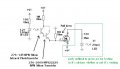
276-145 NPN Silicon Infrared Phototransistor T-1-3/4 case

The MOSFET has more info on the box:
276-2072 IRF510 Power MOSFET Transistor N-channel 60-Volt
I am denoting subscripts like this <subscript>
Maximum Ratings:
V<DSS> = 100V <DM> = 16A
V<GS> = +OR- 20V I<GM> = 1.5A
I<D> = 4A P<D> = 20W
Electrical Characteristics:
I<DSS> = 0.25Ma
v<GS>(th) = 2.0 TO 4.0V
I<D> = 4.0A
R<DS>(on) = 0.6 ohms
g<FS> = 1.0 mhos
c<iss> = 150pf
c<oss> = 100pf
t<d>(on) = 20ns
t<r> = 25ns
t<d>(off) = 25ns
t<f> = 20ns

I don't really understand what all this means. If anyone who does know could tell me if the problem above is the reason the circuit isn't working, please let me know. Or if you see something else wrong, let me know. Thanks.

This picture is exactly how I have everything wired up right now.


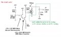
Also, if I hook it up like the picture below, it works perfectly. The only thing is the switch is on when it should be off and off when it should be on.


Attachments

Last edited:

scubasteve_911

Joined Dec 27, 2007
1,203
Hey,

Your resistor value for the phototransistor pullup is far too high. It should be like in the range of 1k-10k, maybe less. Your output impedance is really high and it will take a long time to charge up the gate. Even your pulldown resistor should be decreased, maybe 100K.

I would connect the source to ground, then have the LED and resistor in between the 9V and drain of the FET.

this is all referenced to diagram one. Maybe I am wrong, but this is the way I am seeing it.

Steve

Your VGSth should be fine, 2-4V is reasonable. I doubt the phototransistor's VCE(sat) is past 1.5V.
 

Thread Starter

davidhoff

Joined Sep 19, 2008
66
I made the changes you suggested. I see what you mean about the resistances being too high. I was only thinking about limiting power usage, but I now realize what it was doing to the speed of the switching. I still have the problem of the switch never turning off, though. I'm thinking I might end up changing to the circuit I had in the second picture (with the new resistance values of course) and add an inverter to get the output I'm looking for. Would that work? Or does anyone have any other ideas?
 

scubasteve_911

Joined Dec 27, 2007
1,203
I'm confused why the suggestion doesn't work. Do you have a method to measure the voltage at the gate of the MOSFET under light and without light? This will reveal what is wrong. I don't have the specifications for the parts you are using, so perhaps I am missing something.

Sorry that it didn't work, I am a little surprised they didn't. Maybe I am missing something?

Steve
 

Thread Starter

davidhoff

Joined Sep 19, 2008
66
I actually don't have most of my electronics stuff right now. I'm making this in my dorm, and all my stuff is at home. I think I'm going to go out and buy another multimeter just so I can have one here at school. In response to hgmjr's comment, I only need it to switch on and back off like 15 times per second. It would be nice if it was closer to 50 times per second, but as long as it does 15 it should be fine.
 

scubasteve_911

Joined Dec 27, 2007
1,203
So, you're at a school? Why not try to find some equipment? I've been to both college and university, they have both had a rich supply of oscilloscopes, function generators, many multimeters. Try to make friends with someone in the lab, so that you can have access to a proper workstation.

Steve
 

Thread Starter

davidhoff

Joined Sep 19, 2008
66
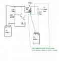
Good News! I got it working! I was sitting around tinkering and I thought of a new way to try it. Below is the working circuit as I now have it set up. EDIT: the NPN transistor is drawn in backwards from the way it is installed. (my bad)


I would like to thank all of you who helped, especially Steve. I learned a LOT from this little project. If anyone notices anything else I should change, I'm always open to suggestions. Thanks everybody!
 

Attachments

Last edited:

scubasteve_911

Joined Dec 27, 2007
1,203
Hi David,

You're very welcome, I'm glad everything work out for you.

Are you powering any significant load with this circuit? If so, the circuit may be hiding a potentially-destructive design error. When switching on and off a load, the MOSFET's gate charge needs to be charged and discharged as soon as possible. When this happens, the transistor is kept out of its linear region. Within this linear region, the transistor will dissipate a massive amount of power.

In order to effectively charge and discharge the transistor's gate, you need to lower the output impedance of the driver circuit. This is done by decreasing both the pullup and pulldown resistances, effectively supplying greater sink and source current.

If you don't have a high current load, then don't worry about these considerations since you will not notice the power loss.

Steve
 

Thread Starter

davidhoff

Joined Sep 19, 2008
66
Today I decided to solder this up on a board, so it would be more permanent. Everything went well until I tested it at the end. Until now I had been running everything off of the same battery just to make things simpler. But now, with one battery powering the switch, and a separate battery powering the load I want to turn on and off, things don't work so well. I reconnected everything with one battery, just to be sure I didn't accidentally change anything, and it worked fine again. So now I'm trying to figure out what is different about using 2 batteries. With the 2 battery setup, it still sort of works. It just takes a long time to switch the load on and off (15+ seconds if the load has been on or off for a while, and less time if you never leave it in one state for too long). Also, the light I'm using to test whether or not the switch is on now fades on and off instead of switching instantly. Is the 2 battery setup I'm trying to use this with even workable?


Attachments

Thread Starter

davidhoff

Joined Sep 19, 2008
66
I tried that while I was fiddling around with it and it does work. The problem is that my test light is not the final application. I want to intercept, or allow to pass, an electronic signal that I don't really know much about except that it is small. So I'm not sure if I can go connecting the battery from the one side to the other.


Attachments

Thread Starter

davidhoff

Joined Sep 19, 2008
66
Would it even matter if there are 2 batteries as long as they were only connected at the negatives? And would that interfere with the signal at all?
 

scubasteve_911

Joined Dec 27, 2007
1,203
I was under the impression that you were switching a high current load. The mosfet doesn't literally act is a switch, it's unidirectional. If your signal is AC or something, then you will half-wave rectify it. If you are only switching small signals, then use an analog switch.

The 4066 is a common analog switch, they're limited to about 25mA sink/source though.

http://www.fairchildsemi.com/ds/MM/MM74HC4066.pdf

For impedance sensitive circuits, they do present a resistance that is a function of the input voltage. This may or may not be an issue, depends on what you're doing really.

You should tell me what you're doing with this, exactly, then maybe I can suggest the best approach. There are other ways to switch, etc.

Steve
 

jpanhalt

Joined Jan 18, 2008
11,087

scubasteve_911

Joined Dec 27, 2007
1,203
John,

Good point, I was wrong to say that. I believe, effectively, current will only flow in one direction in a typical circuit. This is because the gate voltage must be greater than the source by Vth. I suppose for lower voltage circuits, it isn't a big deal.

Is there anyone else that can clear this up?

Steve
 
Top