Inductive proximity sensor / tachometer

Thread Starter

RoyerDominator

Joined Apr 22, 2024
20
What is the make and model number of the flow sensor you have?
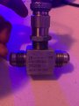
It says "Datarate Murrieta CA 0012001" but I can't find anything online with that description
But this is a website that talks about RF Pickups:
High-Quality Pickup Sensors | Flowmetrics

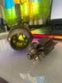
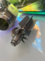
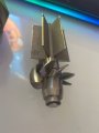
Just to recap, the coil that I have doesn't have any circuit inside it...
You can either get the kind I have (no circuit bare coil)
Or you can get the type that have a built-in circuit.

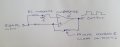
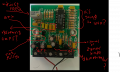
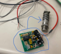
I happen to have the older THT style circuit as shown below. I am trying to reverse engineer it.
I've been successful with a signal generator, but now I need to make my own oscillator.

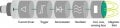
Now with SMD they can fit that whole circuit into the coil as shown in blue

Let me know what you think Mike!
 

Attachments

Thread Starter

RoyerDominator

Joined Apr 22, 2024
20
I am still curious about how this individual is using a differential amplifier as a comparator.
At least that's what it looks like to me.

Using a Hall Effect Sensor to Make a Tachometer - YouTube

You said that you measured the inductance of your "inductive prximity sensor". A hall effect sensor is totally
different, it measures the magnetic field strength (or if a digital hall effect sensor says high or lower than
some built in threshold). And it would not measure as inductive...

It's possible that the signal output from your inductive sensor is in the mV range so make sure your scope can
see signals that low. Or put some A/C gain in front of the scope to increase the signal. This is still quite simple as
there will be NO signal between blades passing the sensor.

Or you have something else, you've refered to things all over the web but never said what you actually have.
Make & Model number... (and URL?)
I just replied Mike.
Waiting on your response when you get a chance ✌
 

michael8

Joined Jan 11, 2015
472
the NTE987 sounds like an lm324 quad op-amp (single supply, cheap, old but still used)

I'm guessing that the circut board was made by "datarate inc" but the metal sensor by someone
else. Does the metal sensor have any id on it? Also what does the end of the gray cable
look like (number of wires? shield?)? Were they orginally connected?
 

MisterBill2

Joined Jan 23, 2018
27,522
There is another method of using a coil wound around a ferrous core that is not magnetized. That is known as a variable reluctance pickup. Using the high frequency excitation is one scheme, but a simpler scheme will run a small DC current thru the coil, and as the ferrous, or even just conductive, tooth passes by the variation in conductivity passing thru the magnetic field will generate a voltage.
 

Thread Starter

RoyerDominator

Joined Apr 22, 2024
20
the NTE987 sounds like an lm324 quad op-amp (single supply, cheap, old but still used)

I'm guessing that the circut board was made by "datarate inc" but the metal sensor by someone
else. Does the metal sensor have any id on it? Also what does the end of the gray cable
look like (number of wires? shield?)? Were they orginally connected?
The flowmeter is made by datarate
The sensor does not have any prints on it, but I'm pretty sure that its just an inductor inside
The end of the grey wire has 2 wires and a shield
yes, originally the 2 wires of the sensor go into that board
Also that grey pot changes the frequency
They are using 38~40khz to excite the coil and the shape looks like a sine/traingle
But with my circuit I am getting away with a square wave and the the few components I described in the very 1st post
Please look at the images below and let me know if you have any other concerns
 

Attachments

Last edited:

Thread Starter

RoyerDominator

Joined Apr 22, 2024
20
There is another method of using a coil wound around a ferrous core that is not magnetized. That is known as a variable reluctance pickup. Using the high frequency excitation is one scheme, but a simpler scheme will run a small DC current thru the coil, and as the ferrous, or even just conductive, tooth passes by the variation in conductivity passing thru the magnetic field will generate a voltage.
Hi Mr.Bill,
Thank you for the input!
I thought exciting an inductor with DC would make it act like a magnet?
And exciting an inductor with AC will cause eddy currents in the metals that we are trying to detect?
So we should use AC in this application?
 

LesJones

Joined Jan 8, 2017
4,511
In your picture I can't see the relationship of the coil to the turbine blade.
My understanding is that you want to avoid sensors that use that use a magnetic field ( variable reluctance or hall effect.) so that the free rotation of the turbine is not effected.
Are you just trying to replicate the circuit board that you show in post #25 ?
As you have the circuit board why not trace out the schematic to understand how it works.
My initial understanding was that you had wound the coil yourself.

Les.
 

Thread Starter

RoyerDominator

Joined Apr 22, 2024
20
In your picture I can't see the relationship of the coil to the turbine blade.
My understanding is that you want to avoid sensors that use that use a magnetic field ( variable reluctance or hall effect.) so that the free rotation of the turbine is not effected.
Are you just trying to replicate the circuit board that you show in post #25 ?
As you have the circuit board why not trace out the schematic to understand how it works.
My initial understanding was that you had wound the coil yourself.

Les.
Yes, I am trying to make that circuit but not replicate it.
Right I didn't make the coil myself. The coil is from some company but there is no print on it.
To be honest I don't want to replicate that circuit. I just want to make my version of it.
I have never traced a circuit before and I don't plan on doing that as of now. Maybe in the near future.

The concept is not that "hard" in my opinion.
1. You have coil, which is the sensor.
2. You create an oscillator to excite the coil in order to detect metals ( square wave is what I'm going with)
3. You have a detector stage, which is the demodulator, keeping track of the voltage amplitude (diode, cap, resitor)
4. Finally you have the output, which can be (comparator/schmitt trigger/adc microcontroller)

Everything is working fine but my problem is the little voltage difference of 100mV
Instead of having the comparatpr work with such a small difference 3.3v to 3.2v
I want it to be for example 0v to 1v or 2v to 3v...
Others have suggested for me to amplify the signal but I dont know where I would do that... like during what stage?

Here are some pictures for a visual view
 

Attachments

Sensacell

Joined Jun 19, 2012
3,785
Hi Mr.Bill,
Thank you for the input!
I thought exciting an inductor with DC would make it act like a magnet?
And exciting an inductor with AC will cause eddy currents in the metals that we are trying to detect?
So we should use AC in this application?
At any rate, you have a magnetic field interacting with the rotor, however tiny it might be.
Don't worry too much about the magnetic field messing with the rotor.

IF the rotor is made of a ferrous magnetic material, I would try the DC excitation first.

IF the rotor is NOT ferrous, then it's time to mess with the complexities of AC modulation, etc.

Since the disassembled photo shows a solid metal barrier between the sensor and rotor compartments, I am going to guess that the housing is stainless and the rotor is ferromagnetic?
You will get eddy currents in the housing too.

If your current scheme is working, why not make a "tracking discriminator" - if you integrate the signal with a long time constant RC filter, then feed both the filtered and unfiltered signals to a comparator, you can extract the 100 mV wiggle without having to adjust anything.
 
Last edited:

Thread Starter

RoyerDominator

Joined Apr 22, 2024
20
At any rate, you have a magnetic field interacting with the rotor, however tiny it might be.
Don't worry too much about the magnetic field messing with the rotor.

IF the rotor is made of a ferrous magnetic material, I would try the DC excitation first.

IF the rotor is NOT ferrous, then it's time to mess with the complexities of AC modulation, etc.

Since the disassembled photo shows a solid metal barrier between the sensor and rotor compartments, I am going to guess that the housing is stainless and the rotor is ferromagnetic?
You will get eddy currents in the housing too.
Yes, Sensacell you are absolutely right about the housing being stainless steel and the turbine blade tips are ferromagnetic!

Sure, I can try the DC excitation but my setup is already working with the AC excitation...

Everything is fine, its just that my comparator is having a hard time working with the small change of 100mv going from 3.3v when there is no blade present and 3.2v when the blade is present..

I have to adjust the amplitude of the square wave down to the 3rd digit to have it working..

I was thinking of this:
The voltage goes from 3.3V down to 3.2v
So can I give a negative gain to make it go from 3.3v down to 0V?
It seems like this individual is doing just that
Using a Hall Effect Sensor to Make a Tachometer (youtube.com)

skip to 7 minutes if you have time
 

Thread Starter

RoyerDominator

Joined Apr 22, 2024
20
At any rate, you have a magnetic field interacting with the rotor, however tiny it might be.
Don't worry too much about the magnetic field messing with the rotor.

IF the rotor is made of a ferrous magnetic material, I would try the DC excitation first.

IF the rotor is NOT ferrous, then it's time to mess with the complexities of AC modulation, etc.

Since the disassembled photo shows a solid metal barrier between the sensor and rotor compartments, I am going to guess that the housing is stainless and the rotor is ferromagnetic?
You will get eddy currents in the housing too.

If your current scheme is working, why not make a "tracking discriminator" - if you integrate the signal with a long time constant RC filter, then feed both the filtered and unfiltered signals to a comparator, you can extract the 100 mV wiggle without having to adjust anything.
My apologies I didn't see what you suggested at the end.

"tracking discriminator" - if you integrate the signal with a long time constant RC filter, then feed both the filtered and unfiltered signals to a comparator, you can extract the 100 mV wiggle without having to adjust anything.

Can you please expand on this?
Do you want me to use an op-amp as an integrator?
I am pretty new to design, this went over my head

Here is a demo...
My problem is that I have to adjust the amplitude of my square wave to be really close to 3.3V which is my vref for the comparator
The amplitude on the square wave is 3.362 volts as seen in the video
AHHH man ;/ I guess I can't upload videos on here...bummer
 

Attachments

Last edited:

Sensacell

Joined Jun 19, 2012
3,785
Here is the problem, you have a small AC signal that rides on top of some totally unpredictable DC voltage.

You try to tweak the signal generator to some exact level - the threshold of your comparator, and it drifts and stops working.

So let the comparator threshold adjust, so it tracks the DC bias level, the AC part feeds the other input and it happily switches.
A bit of positive feedback prevents it from making jittery extra pulses.

The only issue here is when the rotor sits idle for a while, it might glitch for a second or two, until the reference settles in.
The integrator time constant sets the compromise between recovery time and minimum recoverable pulse rate - your choice.
 

Attachments

LesJones

Joined Jan 8, 2017
4,511
A tracking discriminator filters out the pulses from the waveform so you get the average level of the signal. This filtered signal will adjust to compensate for the slowly varying drive level. This signal is now the reference voltage to your comparator. The unfiltered signal will have the pulses on top of the average level. So the comparator is comparing the average level with the average level plus the pulses.
Another approach would be to differentiate the incoming signal so that you only see the pulses.
You seem to be trying to solve the problem with NO FACTS. You do not seem to know what the turbine looks like and the characteristics of the material that it made from. You are just guessing that the sensor is just a coil.
Why to want to make a interface that is functualy the same as the original BUT NOT A CLONE of it ?
You can't dismantle the sensor but you could work out how the original interface works by reverse engineering it. I looks like it is just a 2 layer board so it should be easy to trace out the schematic.
Even if you can't understand how it works I think members of the forum will be able to do so.
This is a link to a tachometer design that gives examples of interfacing hall sensors and reflective opto sensors to logic levels.
http://lesjhobbies.weebly.com/simple-tachometer-for-1-to-99-pulses-per-rev.html
The sensor mounting section shows pictures of hall gear tooth sensors, a small surface mount hall sensor and a reflective opto sensor. For a sense of scale the opto sensor and surface mount hall sensor are mounted on the end of 1/4" diameter paxolin rod.
Les.
 
Last edited:

Thread Starter

RoyerDominator

Joined Apr 22, 2024
20
Here is the problem, you have a small AC signal that rides on top of some totally unpredictable DC voltage.

You try to tweak the signal generator to some exact level - the threshold of your comparator, and it drifts and stops working.

So let the comparator threshold adjust, so it tracks the DC bias level, the AC part feeds the other input and it happily switches.
A bit of positive feedback prevents it from making jittery extra pulses.

The only issue here is when the rotor sits idle for a while, it might glitch for a second or two, until the reference settles in.
The integrator time constant sets the compromise between recovery time and minimum recoverable pulse rate - your choice.
Sensacell:
I am shocked...how did you know that it drifts and stops working without seeing a demo? That is exactly what's happening!
I just looked at your schematic, do you know what values I choose for the resistors and caps?
When you say "your choice" are you suggesting that I should experiment with the values and see what works?
 

Thread Starter

RoyerDominator

Joined Apr 22, 2024
20
A tracking discriminator filters out the pulses from the waveform so you get the average level of the signal. This filtered signal will adjust to compensate for the slowly varying drive level. This signal is now the reference voltage to your comparator. The unfiltered signal will have the pulses on top of the average level. So the comparator is comparing the average level with the average level plus the pulses.
Another approach would be to differentiate the incoming signal so that you only see the pulses.
You seem to be trying to solve the problem with NO FACTS. You do not seem to know what the turbine looks like and the characteristics of the material that it made from. You are just guessing that the sensor is just a coil.
Why to want to make a interface that is functualy the same as the original BUT NOT A CLONE of it ?
You can't dismantle the sensor but you could work out how the original interface works by reverse engineering it. I looks like it is just a 2 layer board so it should be easy to trace out the schematic.
Even if you can't understand how it works I think members of the forum will be able to do so.
This is a link to a tachometer design that gives examples of interfacing hall sensors and reflective opto sensors to logic levels.
http://lesjhobbies.weebly.com/simple-tachometer-for-1-to-99-pulses-per-rev.html
The sensor mounting section shows pictures of hall gear tooth sensors, a small surface mount hall sensor and a reflective opto sensor. For a sense of scale the opto sensor and surface mount hall sensor are mounted on the end of 1/4" diameter paxolin rod.
Les.
Les:
"Another approach would be to differentiate the incoming signal so that you only see the pulses"
By this do you mean that I should use a differential amplifier or an op-amp differentiator?

You make some great points!
You're right, I don't really understand what's going on under the hood as much as you guys do.
Here are some pictures of the turbine blades if that helps. I happen to have a larger setup.
I agree, I will start to trace out the paths and the components so we can all have a better understanding of what the circuit is doing.m
 

Attachments

MisterBill2

Joined Jan 23, 2018
27,522
I used a similar inductive pickup with a similar flowmeter in a test stand about 18 years ago, I think it was. The issue with a standard pickup is that the magnet slows the turbine and so the calibration is a bit off. Hence the need for a variable reluctance scheme which did not cause a problem.
And the wonderful part of working in the design of industrial testing systems was that every job was a new product. The downside is that smaller companies with only a dozen employees can go broke if the sales guy goofs.
 

Thread Starter

RoyerDominator

Joined Apr 22, 2024
20
I used a similar inductive pickup with a similar flowmeter in a test stand about 18 years ago, I think it was. The issue with a standard pickup is that the magnet slows the turbine and so the calibration is a bit off. Hence the need for a variable reluctance scheme which did not cause a problem.
And the wonderful part of working in the design of industrial testing systems was that every job was a new product. The downside is that smaller companies with only a dozen employees can go broke if the sales guy goofs.
MisterBill2:
Oh wow, that's cool!
Do you remember anything about its design or usage?
Yes, I agree with you on that matter. The industry has steered away from standard pickups that use a magnet. That is what I've heard from several individuals.
I will try to trace out the THT circuit as soon as I can to see what they were using back then.
Here is a close-up of the circuit.
I will reply as soon as I trace things out.
 

Attachments

Top