Ok where to start. I have just had the biggest laugh at myself. Didnt see the greyed out text that says do NOT begin with HELP!
Apologies people. Like I said, noob here. I have recreated the thread. See below.
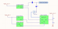
I have attached a picture of a design I am working on.
As the topic states, I would like some help with expert advice on a current project.
I am designing a battery powered IoT sensor Node which will form part of a Mesh network. For my particular use case, there will be little or no human interaction with the device except possibly during installation and response. As such, a core requirement is for the batteries to last as long as possible irrespective of:
Power Demanding RF front-end
Potential prolonged computations
Pseudo real-time sensor measurements from relatively low rated sensors
I designed my power scheme as such:
2 Battery supply sources:
2s1p Alkaline Battery (3v): This is the Normal supply that comes default with the device. It is responsible for powering the whole device (RF, Core & Sensors) in the absence of the other power source.
3v Li Coin Cell: This is going to serve as the supply for the sensors power domain. The idea is for this power supply to complement the other supply by taking control of feeding power to the sensors of the device.
My Intent:
I would like the device to be semi smart by detecting the presence of a battery voltage through the "Power Good" output of a decent boost converter. This will alert the Micro-controller to turn off the P-Channel Mosfet, cutting off power to the sensors sourced from the alkaline battery.
My Dilemma:
As a relative NOOOOOB to this thing, I am still getting my head circuit analysis. I am particularly concerned that the Power Good signal alert, and Mosfet switch will not be completed before the battery voltage is seen at regulators Vout by the circuit. I am not too sure but I would imagine that could cause some interesting electronic undesired effects. That shouldnt be my only dilemma i reckon. But it is my current one.
My Question
Any guidance, advice, hints, tips, tricks on whether this is a sensible solution will go a long way. Also guidance on resistor value selection for the Mosfet.
P.S: Advice on gate drivers and Mosfet modules will also help.
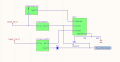
I have attached a picture of an updated schematic design
The new update uses a regulator without a power good feature but an Enable pin. The P_Channel Mosfet (P_msft) will be turned on by res2, ensuring supply to sensor_pow_domain from the Alkaline battery.
Once the complementary cell is placed on coin cell line, this should turn off the mosfet right? I will then implement an RC time delay on the EN pin of the boost converter. This should give ample time for the system to cut power from Alkaline cells to the sensor domain before redirecting its supply source to the coin cell.
Is this electronically sensible? Are there still things I am not seeing based on my use case?
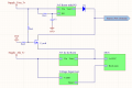
Here again with yet another potential solution for my power requirements.
I have decided to go for a more soft approach until it may be necessary to implement it in hardware. The latest approach will give the responsibility to the Micro controller.
The new approach involves using a basic resistor divider circuit to read the coin cell battery voltage using the Micro controllers ADC. When a voltage is read by the ADC, the MCU first switches OFF the transistor, then turns on the second boost converter through its enable pin.
This software routine will be user initiated when:
User is provisioning a node as a "High Power Node" in the mesh network
User would like to provide complementary power support for other use cases.
Perusing through several datasheets for boost converters, I observe the current consumption for the enable pins are usually in the microamps ranges (i believe I saw some in nanoamps region).
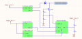
Got another solution that popped into my noggin while doing some fact finding.
I stumbled on an idea called "ganging" (interestingly named if i may add). If i got it, it involves chaining gpio pins together to increase the total drive strength to power what ever circuit needs to be powered. And if i am not mistaken, this can be simply achieved by shorting the pins.
It led me to the next solution which I will have to admit might be the most efficient solution if it is electronically feasible. The sensors are relatively low power sensors, with average running current ranging from 100s of microamps to 10s of milliamps.
I am particularly worried however about specific sensors that require a substantial amount of current for a particular purpose. For example, I will be using a temperature sensor that has a self maintaining heating element to reduce the potential of humidity and moisture in the sensor circuit. This heating element draws as much as 90mA.
Same thing applies as last time, except I am not using a MOSFET anymore. Please help guys. I might just fabricate all of them.
Here again with yet another potential solution for my power requirements.
I have decided to go for a more soft approach until it may be necessary to implement it in hardware. The latest approach will give the responsibility to the Micro controller.
The new approach involves using a basic resistor divider circuit to read the coin cell battery voltage using the Micro controllers ADC. When a voltage is read by the ADC, the MCU first switches OFF the transistor, then turns on the second boost converter through its enable pin.
This software routine will be user initiated when:
User is provisioning a node as a "High Power Node" in the mesh network
User would like to provide complementary power support for other use cases.
Perusing through several datasheets for boost converters, I observe the current consumption for the enable pins are usually in the microamps ranges (i believe I saw some in nanoamps region).
 Facebook
 Google
 GitHub
 Linkedin
")