Inconsistent results in LTSpice input impedance measurements

Thread Starter

Ángel_1487627185

Joined Feb 20, 2017
5
Hi all,

I'm trying to measure several input impedances of an amplifier in LTSpice, using these two methods:

  • AC Voltage source (Vs) at the test point (vin), AC sweep, and a linear plot of V(vin)/I(Vs)
  • AC current source (Is) at the test point (vin), AC sweep, and a linear plot of V(vin)/I(Is)

As far as I knew, the results shoud be the same in either case, but they differ a lot.

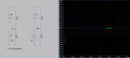
The circuit I'm testing has several stages but, for the purpose of the analysis, I've tried with this setup where you can see the results:


Capture.PNG

Interestingly enoug, If I remove the BJT section, both methods yield the same result:

Capture3.PNG

What I'm I missing? Is there a method I can use that yields consistent results every time?

Thanks!
 

Attachments

Bordodynov

Joined May 20, 2015
3,180
Hey. Your circuit with a voltage source (from the left) is not right. The voltage source has a zero resistance and shorts the base of the transistor to ground. At the input, you need to put a transient capacitor. The circuit with the current source correctly determines the impedance of the wrong electronic circuit. The base resistor is too small and the transistor is in the key mode (not amplified, in saturation mode). Although, maybe you're up to it.
See
2018-01-31_08-32-39.png
2018-01-31_08-43-04.png
 
Last edited:

Thread Starter

Ángel_1487627185

Joined Feb 20, 2017
5
The BJT is not that important, you could use an S9018 or the like.

Bordodynov, I get your point but, nevertheless, the impedance graphs in the circuit with the voltage source Vs are right.

I've found something insteresting. If you short the DC sources (V1..Vn), every circuit yields the same impedance results. Then, it's the circuit with a current source and a not shorted DC source that generates a different result. That makes sense, as shorting DC sources is what one would do when calculating AC impedances by hand. But, didn't LTSPICE take care of this for you, given the DC sources have not a defined AC signal?

Plus, why it doesn't happen in the circuit without BJT?
 

Bordodynov

Joined May 20, 2015
3,180
Because the transistor cardinally changes the (non-linear device) input impedance. In this case, the DC mode is essentially different and different impedance of the transistor. For a voltage source, only the nonlinear capacitances of the collector and the emitter (the transistor is closed) affect. Look at the voltage in the first figure. I did not in vain bring it.
 

Bordodynov

Joined May 20, 2015
3,180
hi,
I don't have the BF199 model, is it OK to use an alternative.?:rolleyes:
E
I try to have all the necessary models for electronic circuits, drawn in the program LTpice. If I do not have any models, then I attach them to my library for LTspice. Therefore, I regularly expand my library. Mentioned transistors are in my library, like many others. I do not like restrictions. You can find my library on
https://forum.allaboutcircuits.com/...nents-models-of-ltspice-free-download.133690/
 
Top