INA125 design to use

Thread Starter

davidbr

Joined Apr 25, 2018
60
Hi all,

FIrst of all I want to tel that my knowledge in this area is quite limited so please be gentle if I ask stupid questions :)

I work on a school project where I need to build a gauge with 4 load cells. I am using 4 x ina125P (one for each sensor) and read data using arduino and sent it to a database.

Now, this is what I have done :

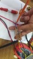
1 - This is load cell (I have 4 of them) - load-cell.jpg

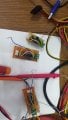
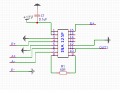
2 - this is how I am using ina 125 (I have 4 of this made on a test pcb) - ina.png

So each ina is wired to one sensor. Now the questions:

1 - When I measure output of each ina, on 2 of them I have around 80-100mV and on 2 of them I have around 150-170 mV. Is that normal? The measurement is made when sensors are in repaus mode.

2 - I saw here on forum some schematics which use some transistors and also some resistors. Is the way that I am using ina the correct one or can you suggest me other schematic?

3 - Where I should wire the shield of the sensors? To the ground?

Thank you very much .

Thank you very much in advance
 

Attachments

Last edited:

Thread Starter

davidbr

Joined Apr 25, 2018
60
Hi,
1 - To be honest I don t know to answer to that question...I am not sure I understand what gain means and this value of 10R was found in a schematic on google.
2 - That s a mistake - I edited post now. I measure mV not mA .
 

ericgibbs

Joined Jan 29, 2010
18,865
hi,
You are using a 10V excitation voltage for the bridge.
The Load Cell datasheet says 3mV/V so on full load the LC[load cell] will output 10 * 3mV =30mV.
The 10R on the Gain pins [ using the Gain formula] gives an output of 6000 * 0.03v = 180V .!!!

Change the 10R , for testing to say 1000R , gain ~ 60, at full load you should measure 1.8V on pin 10 Vo.

When running most INA's on a single voltage supply the Vout will not be 0V, it will be around 0.2v thru 0.5v, when the bridge output is 0mV.

E

EDIT:
You should always read the d/s for any new device that you plan to use.
The answer to the Vout query is here.
AA1 16-Jul-18 09.29.gif
 
Last edited:

Thread Starter

davidbr

Joined Apr 25, 2018
60
Thank you very much for you rexplanation.
For reading voltage I am using ina226 which is capable to read 0-36V. I don t know if that matter but is better to give you all details.
Do you think the schematic I am using is ok? Can I improve it somehow or just change the gain resistor ?
Thanks a lot

L.E. - for example in this schematic there is a transistor and also another 10k resistor..why they are used here?
 

Attachments

ericgibbs

Joined Jan 29, 2010
18,865
hi,
I know the d/s [ datasheet] says 36v , but don't forget you are using a 12V supply, also you will notice that near maximum Vout the voltage will limit at ~Vsup -1v..
The 10k will pull Vo closer to zero volts at Vbridge = 0mV, I always add a10k or 4k7 load.
The C1 cap is also important for decoupling.
Change the Gain resistor from 10R its much too low a value, use 1k or 510R as shown in your image.

Post some Vout results so that we can check your work.
E

EDIT:
Missed your transistor query.
Its sometimes used to give a higher current drive for the load cell excitation, usually for low resistance bridges. Never needed to use it in my applications.
 
Last edited:

Thread Starter

davidbr

Joined Apr 25, 2018
60
Hi,
I did a test pcb with same schematic I uploaded in first post, but I used gain resistor of 510ohms and added a 10k resistor between pins 10-11 and gnd.
for test I used the same type of sensor like post in first post, except is 2.5 tons (not 5 tons) and have 2mV/V not 3mV/V .
This is what I get without any pressure. If I try apply pressure by hand I can get a very small variation like from 82mV to 82.2-3 mV.
I will do some tests with real load asap I can

Power supply used was 12V rail from a PC power supply

Btw - while I was writing this post, the multimeter now show 81.8 (instead 82) and nothing was touched...Is that normal?

Thanks a lot again
 

Attachments

ericgibbs

Joined Jan 29, 2010
18,865
hi,
I would expect that low level ~+80mV offset from Zero when no load applied to the LC.
A little drift in the Vout is not unusual, possible slight variations in component temperature.
Interesting to see you readings, post when ready.
E
 

Thread Starter

davidbr

Joined Apr 25, 2018
60
I will post them tomorrow for sure after do tests.
In datasheet of ina, at fig 4 there is a TIP29C transistor between pin 4 and sensor. Which is this role? Should I try use it also?
thanks
 

ericgibbs

Joined Jan 29, 2010
18,865
hi d,
Thats a current boost transistor, look at this d/s clip
The LC d/s shows each resistor arm of the bridge is 351R, so with a 10Vext, thats 10v/351R = ~28mA.
Adding the transistor will reduce the load on the INA Vref output.

E
AA1 16-Jul-18 12.52.gif
 

Thread Starter

davidbr

Joined Apr 25, 2018
60
So in my setup does it make sense to add it ?
And another question - what should I do with shield from the load cell? Wiring it to ground ..or?
Thanks
 

ericgibbs

Joined Jan 29, 2010
18,865
hi,
Connect the LC shield to the 0V connection, close to the INA 0V pin, scope the INA Vout voltage/noise with and without the shield connected.
If you are studying the INA125, why don't you run the project with and without the transistor, making observations of the VrefOut and the body temperature of the INA.?
Check the INA d/s for the operating temperature upper limits, consider also the ambient temperature.

As it is a Homework assignment, we cannot give you the complete answer.

E
EDIT:
Look at page #6 of this PDF.
 

Attachments

Last edited:

Thread Starter

davidbr

Joined Apr 25, 2018
60
Hi,
I did some tests and here are the results:
I did 3 test circuits using 3 ina. First I also put a BC337 transistor, second and third without transistor. Gain resistor was 560 ohms on all 3 circuits. Sensor for testing was 2.5t (2mV/V).

I - no load - output between 116.5mV and 117.3mV
50kg = 3.1V
100kg = 6.61V
150kg=10.1V
165kg=11.15V
After this output is blocked at ~11.3V no matter what load to the sensor

II - no load - output oscillating 230-290mV. After grounded the load cell shield get output relatively constant 194-205mV
50kg=2.35V
100kg=4.56V
150kg=6.68V
200kg=8.86V
250kg=10.94V
Again output freeze at 11.3V no matter the load is applied.

III - no load - 126-134mV . After ground shield get 119-121mV
50kg=1.76V
100kg=3.66V
150kg=5.5V
200kg=7.37V
250kg=9.33V
300kg=11.18V
Again output freeze at 11.3V no matter the load is applied.
Are these values normal? I tend to believe they are not...
Why always output is freezing on 11.3 V ?
Thanks
 

ericgibbs

Joined Jan 29, 2010
18,865
Why always output is freezing on 11.3 V ?
Hi David,
Did you read the d/s sheet for the INA125, Vout limit., see this clip. [ you are using a 12V supply]

I did say this earlier.
I know the d/s [ datasheet] says 36v , but don't forget you are using a 12V supply, also you will notice that near maximum Vout the voltage will limit at ~Vsup -1v..
I will check your readings and get back to you.
E
 

Attachments

Thread Starter

davidbr

Joined Apr 25, 2018
60
I read that but : the load cell is 2mV/V , that means at full load, considering my excitation voltage being 10V I should have 20mV. After that, with gain 560 R which means 120 then I should have about 2.4 V ...Probably I miss something
 

ericgibbs

Joined Jan 29, 2010
18,865
hi d,
Your test results are incorrect.

A 2.5ton [2268kg]FSD at 2mV/V with a 10Vdc excitation will only give 20mV, when fully loaded.

The Gain, using a 560R is 4 + 60k/560 = ~110

So for 200kG test weight thats (200kG/2268kG) * 20mVfsd = 1.76mV. [Vo= 0.1936v]

Even with 20mV signal thats only 2.2Vout.

Can you post a photo of the project , lets see what you have wrong.
E


Update:
Checking the web regarding the INA125 using a single supply, it appears to a problem for many users.
 
Last edited:

Thread Starter

davidbr

Joined Apr 25, 2018
60
This is what I tested yesterday,
I am planning build another one today, in few hours...
I will post in few moments schematic I used
 

Attachments

Top