importing GPIO_IOToggle example for STM32F407G

Thread Starter

Embededd

Joined Jun 4, 2025
173
Congratulations. You are getting the hang of it.
My UART transmit and receive functionality is working correctly. I used STM32CubeMX to configure the UART and generate the initialization code. After testing it with a serial terminal, I was able to successfully send and receive data.

My next goal is to interface a DS1307 RTC over I2C. Do you have a DS1307 RTC module, and have you ever interfaced one with an STM32?
 

MrChips

Joined Oct 2, 2009
34,947
My UART transmit and receive functionality is working correctly. I used STM32CubeMX to configure the UART and generate the initialization code. After testing it with a serial terminal, I was able to successfully send and receive data.

My next goal is to interface a DS1307 RTC over I2C. Do you have a DS1307 RTC module, and have you ever interfaced one with an STM32?
You don’t need DS1307 RTC.
STM32F407 has built-in battery powered RTC.
 

Thread Starter

Embededd

Joined Jun 4, 2025
173
You don’t need DS1307 RTC.
STM32F407 has built-in battery powered RTC.
I want to interface the DS1307 because it's the only I2C device I currently have. If I can successfully read and write to the DS1307, I'll know that my I2C hardware connections and communication are working correctly. That's the main reason I want to use it.
 
I am not sure if you are aware, but below interfaces are provided by HAL
Code:
HAL_StatusTypeDef HAL_I2C_Mem_Write_IT(I2C_HandleTypeDef *hi2c, uint16_t DevAddress, uint16_t MemAddress,
                                       uint16_t MemAddSize, uint8_t *pData, uint16_t Size)
HAL_StatusTypeDef HAL_I2C_Mem_Read_IT(I2C_HandleTypeDef *hi2c, uint16_t DevAddress, uint16_t MemAddress,
                                      uint16_t MemAddSize, uint8_t *pData, uint16_t Size)
You can use them.
 

Thread Starter

Embededd

Joined Jun 4, 2025
173
I configured I2C1 in STM32CubeMX for 100 kHz, 7-bit addressing, with the STM32 acting as the I2C master. I connected the DS1307 RTC module as follows:

  • PB6 -> SCL
  • PB7 -> SDA
  • 5V -> VCC
  • GND -> GND
  • 4.7 kΩ pull-up resistor from SCL to VCC
  • 4.7 kΩ pull-up resistor from SDA to VCC

To verify that the DS1307 acknowledged its I2C address, I used HAL_I2C_IsDeviceReady(&hi2c1, (0x68 << 1), 3, 100). Based on the return status, I controlled an onboard LED:

Green LED ON: The DS1307 acknowledged the address (HAL_OK).
Red LED ON: The DS1307 did not acknowledge the address or the I2C communication failed.

During testing, the red LED turned ON, indicating that the DS1307 did not acknowledge its address, so further debugging of the hardware connection and I2C communication is required.

C:
/* USER CODE BEGIN Header */
/**
  ******************************************************************************
  * @file           : main.c
  * @brief          : Main program body
  ******************************************************************************
  * @attention
  *
  * Copyright (c) 2026 STMicroelectronics.
  * All rights reserved.
  *
  * This software is licensed under terms that can be found in the LICENSE file
  * in the root directory of this software component.
  * If no LICENSE file comes with this software, it is provided AS-IS.
  *
  ******************************************************************************
  */
/* USER CODE END Header */
/* Includes ------------------------------------------------------------------*/
#include "main.h"
#include "usb_host.h"

/* Private includes ----------------------------------------------------------*/
/* USER CODE BEGIN Includes */

/* USER CODE END Includes */

/* Private typedef -----------------------------------------------------------*/
/* USER CODE BEGIN PTD */

/* USER CODE END PTD */

/* Private define ------------------------------------------------------------*/
/* USER CODE BEGIN PD */

/* USER CODE END PD */

/* Private macro -------------------------------------------------------------*/
/* USER CODE BEGIN PM */

/* USER CODE END PM */

/* Private variables ---------------------------------------------------------*/
I2C_HandleTypeDef hi2c1;

I2S_HandleTypeDef hi2s3;

SPI_HandleTypeDef hspi1;

/* USER CODE BEGIN PV */

/* USER CODE END PV */

/* Private function prototypes -----------------------------------------------*/
void SystemClock_Config(void);
static void MX_GPIO_Init(void);
static void MX_I2C1_Init(void);
static void MX_I2S3_Init(void);
static void MX_SPI1_Init(void);
void MX_USB_HOST_Process(void);

/* USER CODE BEGIN PFP */

/* USER CODE END PFP */

/* Private user code ---------------------------------------------------------*/
/* USER CODE BEGIN 0 */

/* USER CODE END 0 */

/**
  * @brief  The application entry point.
  * @retval int
  */
int main(void)
{

  /* USER CODE BEGIN 1 */

  /* USER CODE END 1 */

  /* MCU Configuration--------------------------------------------------------*/

  /* Reset of all peripherals, Initializes the Flash interface and the Systick. */
  HAL_Init();

  /* USER CODE BEGIN Init */

  /* USER CODE END Init */

  /* Configure the system clock */
  SystemClock_Config();

  /* USER CODE BEGIN SysInit */

  /* USER CODE END SysInit */

  /* Initialize all configured peripherals */
  MX_GPIO_Init();
  MX_I2C1_Init();
  MX_I2S3_Init();
  MX_SPI1_Init();
  MX_USB_HOST_Init();
  /* USER CODE BEGIN 2 */
  HAL_StatusTypeDef status;

  status = HAL_I2C_IsDeviceReady(&hi2c1, (0x68 << 1), 3, 100);
  /* USER CODE END 2 */

  /* Infinite loop */
  /* USER CODE BEGIN WHILE */
  while (1)
  {
    /* USER CODE END WHILE */
    //MX_USB_HOST_Process();

    /* USER CODE BEGIN 3 */
      if (status == HAL_OK)
          {
              /* DS1307 acknowledged its address */
              HAL_GPIO_WritePin(GPIOD, GPIO_PIN_12, GPIO_PIN_SET);   // Green LED ON
          }
          else
          {
              /* DS1307 did not acknowledge */
              HAL_GPIO_WritePin(GPIOD, GPIO_PIN_14, GPIO_PIN_SET);   // Red LED ON
          }
  }
  /* USER CODE END 3 */
}

/**
  * @brief System Clock Configuration
  * @retval None
  */
void SystemClock_Config(void)
{
  RCC_OscInitTypeDef RCC_OscInitStruct = {0};
  RCC_ClkInitTypeDef RCC_ClkInitStruct = {0};

  /** Configure the main internal regulator output voltage
  */
  __HAL_RCC_PWR_CLK_ENABLE();
  __HAL_PWR_VOLTAGESCALING_CONFIG(PWR_REGULATOR_VOLTAGE_SCALE1);

  /** Initializes the RCC Oscillators according to the specified parameters
  * in the RCC_OscInitTypeDef structure.
  */
  RCC_OscInitStruct.OscillatorType = RCC_OSCILLATORTYPE_HSE;
  RCC_OscInitStruct.HSEState = RCC_HSE_ON;
  RCC_OscInitStruct.PLL.PLLState = RCC_PLL_ON;
  RCC_OscInitStruct.PLL.PLLSource = RCC_PLLSOURCE_HSE;
  RCC_OscInitStruct.PLL.PLLM = 8;
  RCC_OscInitStruct.PLL.PLLN = 336;
  RCC_OscInitStruct.PLL.PLLP = RCC_PLLP_DIV2;
  RCC_OscInitStruct.PLL.PLLQ = 7;
  if (HAL_RCC_OscConfig(&RCC_OscInitStruct) != HAL_OK)
  {
    Error_Handler();
  }

  /** Initializes the CPU, AHB and APB buses clocks
  */
  RCC_ClkInitStruct.ClockType = RCC_CLOCKTYPE_HCLK|RCC_CLOCKTYPE_SYSCLK
                              |RCC_CLOCKTYPE_PCLK1|RCC_CLOCKTYPE_PCLK2;
  RCC_ClkInitStruct.SYSCLKSource = RCC_SYSCLKSOURCE_PLLCLK;
  RCC_ClkInitStruct.AHBCLKDivider = RCC_SYSCLK_DIV1;
  RCC_ClkInitStruct.APB1CLKDivider = RCC_HCLK_DIV4;
  RCC_ClkInitStruct.APB2CLKDivider = RCC_HCLK_DIV2;

  if (HAL_RCC_ClockConfig(&RCC_ClkInitStruct, FLASH_LATENCY_5) != HAL_OK)
  {
    Error_Handler();
  }
}

/**
  * @brief I2C1 Initialization Function
  * @param None
  * @retval None
  */
static void MX_I2C1_Init(void)
{

  /* USER CODE BEGIN I2C1_Init 0 */

  /* USER CODE END I2C1_Init 0 */

  /* USER CODE BEGIN I2C1_Init 1 */

  /* USER CODE END I2C1_Init 1 */
  hi2c1.Instance = I2C1;
  hi2c1.Init.ClockSpeed = 100000;
  hi2c1.Init.DutyCycle = I2C_DUTYCYCLE_2;
  hi2c1.Init.OwnAddress1 = 0;
  hi2c1.Init.AddressingMode = I2C_ADDRESSINGMODE_7BIT;
  hi2c1.Init.DualAddressMode = I2C_DUALADDRESS_DISABLE;
  hi2c1.Init.OwnAddress2 = 0;
  hi2c1.Init.GeneralCallMode = I2C_GENERALCALL_DISABLE;
  hi2c1.Init.NoStretchMode = I2C_NOSTRETCH_DISABLE;
  if (HAL_I2C_Init(&hi2c1) != HAL_OK)
  {
    Error_Handler();
  }
  /* USER CODE BEGIN I2C1_Init 2 */

  /* USER CODE END I2C1_Init 2 */

}

/**
  * @brief I2S3 Initialization Function
  * @param None
  * @retval None
  */
static void MX_I2S3_Init(void)
{

  /* USER CODE BEGIN I2S3_Init 0 */

  /* USER CODE END I2S3_Init 0 */

  /* USER CODE BEGIN I2S3_Init 1 */

  /* USER CODE END I2S3_Init 1 */
  hi2s3.Instance = SPI3;
  hi2s3.Init.Mode = I2S_MODE_MASTER_TX;
  hi2s3.Init.Standard = I2S_STANDARD_PHILIPS;
  hi2s3.Init.DataFormat = I2S_DATAFORMAT_16B;
  hi2s3.Init.MCLKOutput = I2S_MCLKOUTPUT_ENABLE;
  hi2s3.Init.AudioFreq = I2S_AUDIOFREQ_96K;
  hi2s3.Init.CPOL = I2S_CPOL_LOW;
  hi2s3.Init.ClockSource = I2S_CLOCK_PLL;
  hi2s3.Init.FullDuplexMode = I2S_FULLDUPLEXMODE_DISABLE;
  if (HAL_I2S_Init(&hi2s3) != HAL_OK)
  {
    Error_Handler();
  }
  /* USER CODE BEGIN I2S3_Init 2 */

  /* USER CODE END I2S3_Init 2 */

}

/**
  * @brief SPI1 Initialization Function
  * @param None
  * @retval None
  */
static void MX_SPI1_Init(void)
{

  /* USER CODE BEGIN SPI1_Init 0 */

  /* USER CODE END SPI1_Init 0 */

  /* USER CODE BEGIN SPI1_Init 1 */

  /* USER CODE END SPI1_Init 1 */
  /* SPI1 parameter configuration*/
  hspi1.Instance = SPI1;
  hspi1.Init.Mode = SPI_MODE_MASTER;
  hspi1.Init.Direction = SPI_DIRECTION_2LINES;
  hspi1.Init.DataSize = SPI_DATASIZE_8BIT;
  hspi1.Init.CLKPolarity = SPI_POLARITY_LOW;
  hspi1.Init.CLKPhase = SPI_PHASE_1EDGE;
  hspi1.Init.NSS = SPI_NSS_SOFT;
  hspi1.Init.BaudRatePrescaler = SPI_BAUDRATEPRESCALER_2;
  hspi1.Init.FirstBit = SPI_FIRSTBIT_MSB;
  hspi1.Init.TIMode = SPI_TIMODE_DISABLE;
  hspi1.Init.CRCCalculation = SPI_CRCCALCULATION_DISABLE;
  hspi1.Init.CRCPolynomial = 10;
  if (HAL_SPI_Init(&hspi1) != HAL_OK)
  {
    Error_Handler();
  }
  /* USER CODE BEGIN SPI1_Init 2 */

  /* USER CODE END SPI1_Init 2 */

}

/**
  * @brief GPIO Initialization Function
  * @param None
  * @retval None
  */
static void MX_GPIO_Init(void)
{
  GPIO_InitTypeDef GPIO_InitStruct = {0};
  /* USER CODE BEGIN MX_GPIO_Init_1 */

  /* USER CODE END MX_GPIO_Init_1 */

  /* GPIO Ports Clock Enable */
  __HAL_RCC_GPIOE_CLK_ENABLE();
  __HAL_RCC_GPIOC_CLK_ENABLE();
  __HAL_RCC_GPIOH_CLK_ENABLE();
  __HAL_RCC_GPIOA_CLK_ENABLE();
  __HAL_RCC_GPIOB_CLK_ENABLE();
  __HAL_RCC_GPIOD_CLK_ENABLE();

  /*Configure GPIO pin Output Level */
  HAL_GPIO_WritePin(CS_I2C_SPI_GPIO_Port, CS_I2C_SPI_Pin, GPIO_PIN_RESET);

  /*Configure GPIO pin Output Level */
  HAL_GPIO_WritePin(OTG_FS_PowerSwitchOn_GPIO_Port, OTG_FS_PowerSwitchOn_Pin, GPIO_PIN_SET);

  /*Configure GPIO pin Output Level */
  HAL_GPIO_WritePin(GPIOD, LD4_Pin|LD3_Pin|LD5_Pin|LD6_Pin
                          |Audio_RST_Pin, GPIO_PIN_RESET);

  /*Configure GPIO pin : CS_I2C_SPI_Pin */
  GPIO_InitStruct.Pin = CS_I2C_SPI_Pin;
  GPIO_InitStruct.Mode = GPIO_MODE_OUTPUT_PP;
  GPIO_InitStruct.Pull = GPIO_NOPULL;
  GPIO_InitStruct.Speed = GPIO_SPEED_FREQ_LOW;
  HAL_GPIO_Init(CS_I2C_SPI_GPIO_Port, &GPIO_InitStruct);

  /*Configure GPIO pin : OTG_FS_PowerSwitchOn_Pin */
  GPIO_InitStruct.Pin = OTG_FS_PowerSwitchOn_Pin;
  GPIO_InitStruct.Mode = GPIO_MODE_OUTPUT_PP;
  GPIO_InitStruct.Pull = GPIO_NOPULL;
  GPIO_InitStruct.Speed = GPIO_SPEED_FREQ_LOW;
  HAL_GPIO_Init(OTG_FS_PowerSwitchOn_GPIO_Port, &GPIO_InitStruct);

  /*Configure GPIO pin : PDM_OUT_Pin */
  GPIO_InitStruct.Pin = PDM_OUT_Pin;
  GPIO_InitStruct.Mode = GPIO_MODE_AF_PP;
  GPIO_InitStruct.Pull = GPIO_NOPULL;
  GPIO_InitStruct.Speed = GPIO_SPEED_FREQ_LOW;
  GPIO_InitStruct.Alternate = GPIO_AF5_SPI2;
  HAL_GPIO_Init(PDM_OUT_GPIO_Port, &GPIO_InitStruct);

  /*Configure GPIO pin : B1_Pin */
  GPIO_InitStruct.Pin = B1_Pin;
  GPIO_InitStruct.Mode = GPIO_MODE_EVT_RISING;
  GPIO_InitStruct.Pull = GPIO_NOPULL;
  HAL_GPIO_Init(B1_GPIO_Port, &GPIO_InitStruct);

  /*Configure GPIO pin : BOOT1_Pin */
  GPIO_InitStruct.Pin = BOOT1_Pin;
  GPIO_InitStruct.Mode = GPIO_MODE_INPUT;
  GPIO_InitStruct.Pull = GPIO_NOPULL;
  HAL_GPIO_Init(BOOT1_GPIO_Port, &GPIO_InitStruct);

  /*Configure GPIO pin : CLK_IN_Pin */
  GPIO_InitStruct.Pin = CLK_IN_Pin;
  GPIO_InitStruct.Mode = GPIO_MODE_AF_PP;
  GPIO_InitStruct.Pull = GPIO_NOPULL;
  GPIO_InitStruct.Speed = GPIO_SPEED_FREQ_LOW;
  GPIO_InitStruct.Alternate = GPIO_AF5_SPI2;
  HAL_GPIO_Init(CLK_IN_GPIO_Port, &GPIO_InitStruct);

  /*Configure GPIO pins : LD4_Pin LD3_Pin LD5_Pin LD6_Pin
                           Audio_RST_Pin */
  GPIO_InitStruct.Pin = LD4_Pin|LD3_Pin|LD5_Pin|LD6_Pin
                          |Audio_RST_Pin;
  GPIO_InitStruct.Mode = GPIO_MODE_OUTPUT_PP;
  GPIO_InitStruct.Pull = GPIO_NOPULL;
  GPIO_InitStruct.Speed = GPIO_SPEED_FREQ_LOW;
  HAL_GPIO_Init(GPIOD, &GPIO_InitStruct);

  /*Configure GPIO pin : OTG_FS_OverCurrent_Pin */
  GPIO_InitStruct.Pin = OTG_FS_OverCurrent_Pin;
  GPIO_InitStruct.Mode = GPIO_MODE_INPUT;
  GPIO_InitStruct.Pull = GPIO_NOPULL;
  HAL_GPIO_Init(OTG_FS_OverCurrent_GPIO_Port, &GPIO_InitStruct);

  /*Configure GPIO pin : MEMS_INT2_Pin */
  GPIO_InitStruct.Pin = MEMS_INT2_Pin;
  GPIO_InitStruct.Mode = GPIO_MODE_EVT_RISING;
  GPIO_InitStruct.Pull = GPIO_NOPULL;
  HAL_GPIO_Init(MEMS_INT2_GPIO_Port, &GPIO_InitStruct);

  /* USER CODE BEGIN MX_GPIO_Init_2 */

  /* USER CODE END MX_GPIO_Init_2 */
}

/* USER CODE BEGIN 4 */

/* USER CODE END 4 */

/**
  * @brief  This function is executed in case of error occurrence.
  * @retval None
  */
void Error_Handler(void)
{
  /* USER CODE BEGIN Error_Handler_Debug */
  /* User can add his own implementation to report the HAL error return state */
  __disable_irq();
  while (1)
  {
  }
  /* USER CODE END Error_Handler_Debug */
}
#ifdef USE_FULL_ASSERT
/**
  * @brief  Reports the name of the source file and the source line number
  *         where the assert_param error has occurred.
  * @param  file: pointer to the source file name
  * @param  line: assert_param error line source number
  * @retval None
  */
void assert_failed(uint8_t *file, uint32_t line)
{
  /* USER CODE BEGIN 6 */
  /* User can add his own implementation to report the file name and line number,
     ex: printf("Wrong parameters value: file %s on line %d\r\n", file, line) */
  /* USER CODE END 6 */
}
#endif /* USE_FULL_ASSERT */
 
It can be hardware issue, but few improvements in the code.

Code:
/* USER CODE BEGIN Header */
/**
  ******************************************************************************
  * @file           : main.c
  * @brief          : Main program body
  ******************************************************************************
  * @attention
  *
  * Copyright (c) 2026 STMicroelectronics.
  * All rights reserved.
  *
  * This software is licensed under terms that can be found in the LICENSE file
  * in the root directory of this software component.
  * If no LICENSE file comes with this software, it is provided AS-IS.
  *
  ******************************************************************************
  */
/* USER CODE END Header */
/* Includes ------------------------------------------------------------------*/
#include "main.h"
#include "usb_host.h"

/* Private includes ----------------------------------------------------------*/
/* USER CODE BEGIN Includes */

/* USER CODE END Includes */

/* Private typedef -----------------------------------------------------------*/
/* USER CODE BEGIN PTD */

/* USER CODE END PTD */

/* Private define ------------------------------------------------------------*/
/* USER CODE BEGIN PD */

/* USER CODE END PD */

/* Private macro -------------------------------------------------------------*/
/* USER CODE BEGIN PM */

/* USER CODE END PM */

/* Private variables ---------------------------------------------------------*/
I2C_HandleTypeDef hi2c1;

I2S_HandleTypeDef hi2s3;

SPI_HandleTypeDef hspi1;

/* USER CODE BEGIN PV */

/* USER CODE END PV */

/* Private function prototypes -----------------------------------------------*/
void SystemClock_Config(void);
static void MX_GPIO_Init(void);
static void MX_I2C1_Init(void);
static void MX_I2S3_Init(void);
static void MX_SPI1_Init(void);
void MX_USB_HOST_Process(void);

/* USER CODE BEGIN PFP */

/* USER CODE END PFP */

/* Private user code ---------------------------------------------------------*/
/* USER CODE BEGIN 0 */

/* USER CODE END 0 */

/**
  * @brief  The application entry point.
  * @retval int
  */
int main(void)
{

  /* USER CODE BEGIN 1 */

  /* USER CODE END 1 */

  /* MCU Configuration--------------------------------------------------------*/

  /* Reset of all peripherals, Initializes the Flash interface and the Systick. */
  HAL_Init();

  /* USER CODE BEGIN Init */

  /* USER CODE END Init */

  /* Configure the system clock */
  SystemClock_Config();

  /* USER CODE BEGIN SysInit */

  /* USER CODE END SysInit */

  /* Initialize all configured peripherals */
  MX_GPIO_Init();
  MX_I2C1_Init();
  MX_I2S3_Init();
  MX_SPI1_Init();
  MX_USB_HOST_Init();
  /* USER CODE BEGIN 2 */
  HAL_StatusTypeDef status;

  status = HAL_I2C_IsDeviceReady(&hi2c1, (0x68 << 1), 3, 100);
  HAL_Delay(1000);
  if (status == HAL_OK)
  {
              /* DS1307 acknowledged its address */
              HAL_GPIO_WritePin(GPIOD, GPIO_PIN_12, GPIO_PIN_SET);   // Green LED ON
  }
  else
  {
              /* DS1307 did not acknowledge */
              HAL_GPIO_WritePin(GPIOD, GPIO_PIN_14, GPIO_PIN_SET);   // Red LED ON
   }
  /* USER CODE END 2 */

  /* Infinite loop */
  /* USER CODE BEGIN WHILE */
  while (1)
  {
    /* USER CODE END WHILE */
    //MX_USB_HOST_Process();

    /* USER CODE BEGIN 3 */
      
  }
  /* USER CODE END 3 */
}

/**
  * @brief System Clock Configuration
  * @retval None
  */
void SystemClock_Config(void)
{
  RCC_OscInitTypeDef RCC_OscInitStruct = {0};
  RCC_ClkInitTypeDef RCC_ClkInitStruct = {0};

  /** Configure the main internal regulator output voltage
  */
  __HAL_RCC_PWR_CLK_ENABLE();
  __HAL_PWR_VOLTAGESCALING_CONFIG(PWR_REGULATOR_VOLTAGE_SCALE1);

  /** Initializes the RCC Oscillators according to the specified parameters
  * in the RCC_OscInitTypeDef structure.
  */
  RCC_OscInitStruct.OscillatorType = RCC_OSCILLATORTYPE_HSE;
  RCC_OscInitStruct.HSEState = RCC_HSE_ON;
  RCC_OscInitStruct.PLL.PLLState = RCC_PLL_ON;
  RCC_OscInitStruct.PLL.PLLSource = RCC_PLLSOURCE_HSE;
  RCC_OscInitStruct.PLL.PLLM = 8;
  RCC_OscInitStruct.PLL.PLLN = 336;
  RCC_OscInitStruct.PLL.PLLP = RCC_PLLP_DIV2;
  RCC_OscInitStruct.PLL.PLLQ = 7;
  if (HAL_RCC_OscConfig(&RCC_OscInitStruct) != HAL_OK)
  {
    Error_Handler();
  }

  /** Initializes the CPU, AHB and APB buses clocks
  */
  RCC_ClkInitStruct.ClockType = RCC_CLOCKTYPE_HCLK|RCC_CLOCKTYPE_SYSCLK
                              |RCC_CLOCKTYPE_PCLK1|RCC_CLOCKTYPE_PCLK2;
  RCC_ClkInitStruct.SYSCLKSource = RCC_SYSCLKSOURCE_PLLCLK;
  RCC_ClkInitStruct.AHBCLKDivider = RCC_SYSCLK_DIV1;
  RCC_ClkInitStruct.APB1CLKDivider = RCC_HCLK_DIV4;
  RCC_ClkInitStruct.APB2CLKDivider = RCC_HCLK_DIV2;

  if (HAL_RCC_ClockConfig(&RCC_ClkInitStruct, FLASH_LATENCY_5) != HAL_OK)
  {
    Error_Handler();
  }
}

/**
  * @brief I2C1 Initialization Function
  * @param None
  * @retval None
  */
static void MX_I2C1_Init(void)
{

  /* USER CODE BEGIN I2C1_Init 0 */

  /* USER CODE END I2C1_Init 0 */

  /* USER CODE BEGIN I2C1_Init 1 */

  /* USER CODE END I2C1_Init 1 */
  hi2c1.Instance = I2C1;
  hi2c1.Init.ClockSpeed = 100000;
  hi2c1.Init.DutyCycle = I2C_DUTYCYCLE_2;
  hi2c1.Init.OwnAddress1 = 0;
  hi2c1.Init.AddressingMode = I2C_ADDRESSINGMODE_7BIT;
  hi2c1.Init.DualAddressMode = I2C_DUALADDRESS_DISABLE;
  hi2c1.Init.OwnAddress2 = 0;
  hi2c1.Init.GeneralCallMode = I2C_GENERALCALL_DISABLE;
  hi2c1.Init.NoStretchMode = I2C_NOSTRETCH_DISABLE;
  if (HAL_I2C_Init(&hi2c1) != HAL_OK)
  {
    Error_Handler();
  }
  /* USER CODE BEGIN I2C1_Init 2 */

  /* USER CODE END I2C1_Init 2 */

}

/**
  * @brief I2S3 Initialization Function
  * @param None
  * @retval None
  */
static void MX_I2S3_Init(void)
{

  /* USER CODE BEGIN I2S3_Init 0 */

  /* USER CODE END I2S3_Init 0 */

  /* USER CODE BEGIN I2S3_Init 1 */

  /* USER CODE END I2S3_Init 1 */
  hi2s3.Instance = SPI3;
  hi2s3.Init.Mode = I2S_MODE_MASTER_TX;
  hi2s3.Init.Standard = I2S_STANDARD_PHILIPS;
  hi2s3.Init.DataFormat = I2S_DATAFORMAT_16B;
  hi2s3.Init.MCLKOutput = I2S_MCLKOUTPUT_ENABLE;
  hi2s3.Init.AudioFreq = I2S_AUDIOFREQ_96K;
  hi2s3.Init.CPOL = I2S_CPOL_LOW;
  hi2s3.Init.ClockSource = I2S_CLOCK_PLL;
  hi2s3.Init.FullDuplexMode = I2S_FULLDUPLEXMODE_DISABLE;
  if (HAL_I2S_Init(&hi2s3) != HAL_OK)
  {
    Error_Handler();
  }
  /* USER CODE BEGIN I2S3_Init 2 */

  /* USER CODE END I2S3_Init 2 */

}

/**
  * @brief SPI1 Initialization Function
  * @param None
  * @retval None
  */
static void MX_SPI1_Init(void)
{

  /* USER CODE BEGIN SPI1_Init 0 */

  /* USER CODE END SPI1_Init 0 */

  /* USER CODE BEGIN SPI1_Init 1 */

  /* USER CODE END SPI1_Init 1 */
  /* SPI1 parameter configuration*/
  hspi1.Instance = SPI1;
  hspi1.Init.Mode = SPI_MODE_MASTER;
  hspi1.Init.Direction = SPI_DIRECTION_2LINES;
  hspi1.Init.DataSize = SPI_DATASIZE_8BIT;
  hspi1.Init.CLKPolarity = SPI_POLARITY_LOW;
  hspi1.Init.CLKPhase = SPI_PHASE_1EDGE;
  hspi1.Init.NSS = SPI_NSS_SOFT;
  hspi1.Init.BaudRatePrescaler = SPI_BAUDRATEPRESCALER_2;
  hspi1.Init.FirstBit = SPI_FIRSTBIT_MSB;
  hspi1.Init.TIMode = SPI_TIMODE_DISABLE;
  hspi1.Init.CRCCalculation = SPI_CRCCALCULATION_DISABLE;
  hspi1.Init.CRCPolynomial = 10;
  if (HAL_SPI_Init(&hspi1) != HAL_OK)
  {
    Error_Handler();
  }
  /* USER CODE BEGIN SPI1_Init 2 */

  /* USER CODE END SPI1_Init 2 */

}

/**
  * @brief GPIO Initialization Function
  * @param None
  * @retval None
  */
static void MX_GPIO_Init(void)
{
  GPIO_InitTypeDef GPIO_InitStruct = {0};
  /* USER CODE BEGIN MX_GPIO_Init_1 */

  /* USER CODE END MX_GPIO_Init_1 */

  /* GPIO Ports Clock Enable */
  __HAL_RCC_GPIOE_CLK_ENABLE();
  __HAL_RCC_GPIOC_CLK_ENABLE();
  __HAL_RCC_GPIOH_CLK_ENABLE();
  __HAL_RCC_GPIOA_CLK_ENABLE();
  __HAL_RCC_GPIOB_CLK_ENABLE();
  __HAL_RCC_GPIOD_CLK_ENABLE();

  /*Configure GPIO pin Output Level */
  HAL_GPIO_WritePin(CS_I2C_SPI_GPIO_Port, CS_I2C_SPI_Pin, GPIO_PIN_RESET);

  /*Configure GPIO pin Output Level */
  HAL_GPIO_WritePin(OTG_FS_PowerSwitchOn_GPIO_Port, OTG_FS_PowerSwitchOn_Pin, GPIO_PIN_SET);

  /*Configure GPIO pin Output Level */
  HAL_GPIO_WritePin(GPIOD, LD4_Pin|LD3_Pin|LD5_Pin|LD6_Pin
                          |Audio_RST_Pin, GPIO_PIN_RESET);

  /*Configure GPIO pin : CS_I2C_SPI_Pin */
  GPIO_InitStruct.Pin = CS_I2C_SPI_Pin;
  GPIO_InitStruct.Mode = GPIO_MODE_OUTPUT_PP;
  GPIO_InitStruct.Pull = GPIO_NOPULL;
  GPIO_InitStruct.Speed = GPIO_SPEED_FREQ_LOW;
  HAL_GPIO_Init(CS_I2C_SPI_GPIO_Port, &GPIO_InitStruct);

  /*Configure GPIO pin : OTG_FS_PowerSwitchOn_Pin */
  GPIO_InitStruct.Pin = OTG_FS_PowerSwitchOn_Pin;
  GPIO_InitStruct.Mode = GPIO_MODE_OUTPUT_PP;
  GPIO_InitStruct.Pull = GPIO_NOPULL;
  GPIO_InitStruct.Speed = GPIO_SPEED_FREQ_LOW;
  HAL_GPIO_Init(OTG_FS_PowerSwitchOn_GPIO_Port, &GPIO_InitStruct);

  /*Configure GPIO pin : PDM_OUT_Pin */
  GPIO_InitStruct.Pin = PDM_OUT_Pin;
  GPIO_InitStruct.Mode = GPIO_MODE_AF_PP;
  GPIO_InitStruct.Pull = GPIO_NOPULL;
  GPIO_InitStruct.Speed = GPIO_SPEED_FREQ_LOW;
  GPIO_InitStruct.Alternate = GPIO_AF5_SPI2;
  HAL_GPIO_Init(PDM_OUT_GPIO_Port, &GPIO_InitStruct);

  /*Configure GPIO pin : B1_Pin */
  GPIO_InitStruct.Pin = B1_Pin;
  GPIO_InitStruct.Mode = GPIO_MODE_EVT_RISING;
  GPIO_InitStruct.Pull = GPIO_NOPULL;
  HAL_GPIO_Init(B1_GPIO_Port, &GPIO_InitStruct);

  /*Configure GPIO pin : BOOT1_Pin */
  GPIO_InitStruct.Pin = BOOT1_Pin;
  GPIO_InitStruct.Mode = GPIO_MODE_INPUT;
  GPIO_InitStruct.Pull = GPIO_NOPULL;
  HAL_GPIO_Init(BOOT1_GPIO_Port, &GPIO_InitStruct);

  /*Configure GPIO pin : CLK_IN_Pin */
  GPIO_InitStruct.Pin = CLK_IN_Pin;
  GPIO_InitStruct.Mode = GPIO_MODE_AF_PP;
  GPIO_InitStruct.Pull = GPIO_NOPULL;
  GPIO_InitStruct.Speed = GPIO_SPEED_FREQ_LOW;
  GPIO_InitStruct.Alternate = GPIO_AF5_SPI2;
  HAL_GPIO_Init(CLK_IN_GPIO_Port, &GPIO_InitStruct);

  /*Configure GPIO pins : LD4_Pin LD3_Pin LD5_Pin LD6_Pin
                           Audio_RST_Pin */
  GPIO_InitStruct.Pin = LD4_Pin|LD3_Pin|LD5_Pin|LD6_Pin
                          |Audio_RST_Pin;
  GPIO_InitStruct.Mode = GPIO_MODE_OUTPUT_PP;
  GPIO_InitStruct.Pull = GPIO_NOPULL;
  GPIO_InitStruct.Speed = GPIO_SPEED_FREQ_LOW;
  HAL_GPIO_Init(GPIOD, &GPIO_InitStruct);

  /*Configure GPIO pin : OTG_FS_OverCurrent_Pin */
  GPIO_InitStruct.Pin = OTG_FS_OverCurrent_Pin;
  GPIO_InitStruct.Mode = GPIO_MODE_INPUT;
  GPIO_InitStruct.Pull = GPIO_NOPULL;
  HAL_GPIO_Init(OTG_FS_OverCurrent_GPIO_Port, &GPIO_InitStruct);

  /*Configure GPIO pin : MEMS_INT2_Pin */
  GPIO_InitStruct.Pin = MEMS_INT2_Pin;
  GPIO_InitStruct.Mode = GPIO_MODE_EVT_RISING;
  GPIO_InitStruct.Pull = GPIO_NOPULL;
  HAL_GPIO_Init(MEMS_INT2_GPIO_Port, &GPIO_InitStruct);

  /* USER CODE BEGIN MX_GPIO_Init_2 */

  /* USER CODE END MX_GPIO_Init_2 */
}

/* USER CODE BEGIN 4 */

/* USER CODE END 4 */

/**
  * @brief  This function is executed in case of error occurrence.
  * @retval None
  */
void Error_Handler(void)
{
  /* USER CODE BEGIN Error_Handler_Debug */
  /* User can add his own implementation to report the HAL error return state */
  __disable_irq();
  while (1)
  {
  }
  /* USER CODE END Error_Handler_Debug */
}
#ifdef USE_FULL_ASSERT
/**
  * @brief  Reports the name of the source file and the source line number
  *         where the assert_param error has occurred.
  * @param  file: pointer to the source file name
  * @param  line: assert_param error line source number
  * @retval None
  */
void assert_failed(uint8_t *file, uint32_t line)
{
  /* USER CODE BEGIN 6 */
  /* User can add his own implementation to report the file name and line number,
     ex: printf("Wrong parameters value: file %s on line %d\r\n", file, line) */
  /* USER CODE END 6 */
}
#endif /* USE_FULL_ASSERT */
 

Thread Starter

Embededd

Joined Jun 4, 2025
173
It can be hardware issue, but few improvements in the code.
How do you confirm whether the issue is with the hardware rather than the firmware? Have you tested this yourself with an STM32 and a DS1307 using a similar setup? Also, do you have the same hardware configuration? What's your experience working with STM32 and I2C, and whether you've successfully interfaced a DS1307 before.

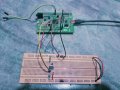
I have already mentioned the connection between the STM32F407G-DISC1 and the DS1307 RTC module in my previous post. For reference, I am attaching a screenshot of my hardware setup.

STM32 with DS1307.jpg
 
How do you confirm whether the issue is with the hardware rather than the firmware? Have you tested this yourself with an STM32 and a DS1307 using a similar setup? Also, do you have the same hardware configuration? What's your experience working with STM32 and I2C, and whether you've successfully interfaced a DS1307 before.

I have already mentioned the connection between the STM32F407G-DISC1 and the DS1307 RTC module in my previous post. For reference, I am attaching a screenshot of my hardware setup.

View attachment 369127
Have you asked AI (Copilot)? I have done a lot with STM32 and had good results when getting guidance from AI recently. I hadn't used AI at all but a few months ago had challenges when working with this device - nRF24L01P (SPI) - AI was instrumental in getting it all working cleanly.

1783270102960.png

e.g.

1783269633469.png

This at least give you another way to explore all this, might shed light on something that you've overlooked...
 
Last edited:

Thread Starter

Embededd

Joined Jun 4, 2025
173
Do you @MrChips have any verified working I2C code that simply sends the slave address and checks whether the slave acknowledges (ACK)? Right now, that's all I'm trying to get working. If you have a working example, could you share it with me? It would help me verify that my I2C hardware setup is functioning correctly before I proceed further.
 

MrChips

Joined Oct 2, 2009
34,947
Do you @MrChips have any verified working I2C code that simply sends the slave address and checks whether the slave acknowledges (ACK)? Right now, that's all I'm trying to get working. If you have a working example, could you share it with me? It would help me verify that my I2C hardware setup is functioning correctly before I proceed further.
Sorry, I don't have any I2C. Have you looked at STM32 I2C examples?
Do you have an oscilloscope?
 
Top