 Facebook
 Google
 GitHub
 Linkedin
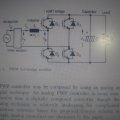
I am studying this circuit which is IGBT based pwm rectifier with power factor control,all theory about sensing the current and output voltage and supplying a respective pwm switching through a feed back make sense to me,but i am caught at one simple thing(mostly my inability to understand).
It is the following
if only pwm pulse should control the current through dc load capacitor which in turn supply load R,I see a short through diode(s1 igbt's) and diode(s3 igbt's) through load R for positive cycle and similarly through other two for negative cycle,what is the explanation,should I never turn off all the switch and should they always be PWM'ed
Attachments
-
 1.8 MB Views: 29


