IGBT DRIVING USING 555 PWM AND IR2101

Thread Starter

jobinjohn90.ece

Joined Sep 18, 2017
9
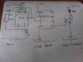
someone please help me to solve the IGBT driving issue ,i am using 555 timer to generate pwm and the output is connected to the input of IR2101 and supply voltage is 12v dc,then iam trying to drive single IGBT(FGA25P) using IR2101 but i can't able to control the IGBT using pwm by varing pot, when iam turned on the power the IGBT is always on ,the output from the 555 and IR2101 shows varing pulse width in CRO,the diagram of the circuit iam attached here,load iam using as a normal incandescent lamp
 

Attachments

shortbus

Joined Sep 30, 2009
10,045
Is it because you have the pots wiper connected to the pin 3 out put of the 555? Won't that always keep the Lin energized?
 

Thread Starter

jobinjohn90.ece

Joined Sep 18, 2017
9
Thanks for all your support, now iam correcting the circuit and get the pwm but some ripples present on it even iam using 470uf across the supplied power and i also need IR2101/04 IGBT driving help ,to drive single FG25P igbt with 220vdc ,iam not expert in English so iam apologizing to any language mistakes
 

Janis59

Joined Aug 21, 2017
1,849
Hi John! I`m John too as You easily may see, and "Lingua Purum" [Den Brown invented term] is not mine mother tongue too however I may be thankful to the fate that my mum was making a choice for me as a kid let the English instead of German will be taught to me at my school time. Thus, feel invited! (from Your personal page I cant see from which part of Planet You are?)
Okay, now about deal: I suspect very hardly that Your problem is due to very characteristic fault of all electrolytes - them are slow and those rare ultra-short network spikes they are not able to suppress at all. One school is teaching that to each 50 mA of 5V power consumption must be added one ceramic 47 to 68 nF "flag" capacitor as near as possible to the receiver tablet (here 555). Even if spikes cause is 555 by itself, it would help. Other more stricter school teaches that any electrolyte say 1000 mkF ought be paralleled with cascade of divided by ten smaller capacitors, at case of illustration 100 mkF 10 mkF 1 mkF 100nF 10 nF 1 nF 100 pF and then ultimately the air will be clean at power wire. You have freedom to shorten this cascade up to 1000-1-0,1-0,01 or even more harsh 1000-0,1-0,01. The reason is hidden in resonance frequency of any capacitor, what are hardly below 1 kHz for ANY except very special electrolytes (it means that OVER this frequency the capacitor converts to the "coil"!!!!!), and most of 0,1 has frequency hardly under few MHz, and 0,01 in few tens of MHz. Anything what is beyond the 10 or with reserve 100 MHz may produce the mal-triggering of Your circuit. The best style is to hang over the RF capacitor in the "second floor" straight over the IC tablet, then the leads length is always effectively minimized to few mm~s.
The other reason what have less probability as prime suspect is wrongly made "ground jobs" or even magnetic-linked troubles. First are coming if the connection to common points (gnd) between capacitor from Nr5 and Nr1 and 0,1 capacitor from Nr8 are not close enough (as an example 5 or 10 mm afar), and if You have a say 10cm the influence will be imminent. Here the most wrong case is if the gnd line makes a closed loop.
Second is how Your PCB tracks are parallel to main current wires. If distance is at least 6cm its OK, if few mm then don`t surprise.
 
Last edited:
Top