Identifying wires of an unknown photo interrupter

Thread Starter

Doros

Joined Dec 17, 2013
144
Hello all,

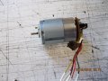
I have a couple of mabuchi motors (from printers) with photointerrupters installed on them. I need the photointerupters for an electric field mill I am trying to construct.

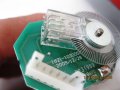
One of them, has 3 wires, and the other (transparent) 4 wires.
Is it feasible to identify the ground, power and the signal?
Of course then I would have to find out the volts needed to power and resistors needed. The transparent one has on the pcb the resistors and capacitors

Thanks for your help

doros
 

Attachments

MisterBill2

Joined Jan 23, 2018
18,179
On the motor with the wire leads, it is quite possible that there is a color code in place that may help. That would be black for the circuit common, red for the positive supply voltage, and yellow as the output signal. If you have a digital multimeter this could be verified, even fairly simply, if that meter has a diode check mode available. The other tool you would need is a source of quite bright light, such as bright sunshine. Determining which leads feed the light source diode, if your meter has a diode check mode, is done by connecting the meter leads across the suspected light source leads. In one direction it will indicate the forward drop of the LED, while in the opposite polarity connection it should show an open circuit. Next, connect the meter across the suspected sensor leads, yellow(+) and black common, and read the resistance. The resistance should vary a bit when the bright light source is directed so that it shines on the sensor from some angle.

But now I have a big question: What is an electric field mill?, AND how is a photo sensor involved with it? I am quite familiar with milling machines, but I have never even heard of an electric field mill. So now I am wondering.
 

DickCappels

Joined Aug 21, 2008
10,152
The odds are that there is one LED and one phototransistor in each interrupter. The LED will have a voltage drop in the range of 1.1 to 1.4 volts when there are a few milliamps going through it. The photo transistor will conduct from collector to emitter -you will probably have to try both polarities but you should be able to see it conducting using an ohmmeter (or DVM set to measure resistance or on diode test setting).
 

Thread Starter

Doros

Joined Dec 17, 2013
144
Thanks MrBill2 and DickCappels. It is an instrument I want to make to measure electrostatic fields. Like the attachment

I will try to identify the diode and transistor the way you proposed.

Concerning power it, and using resistors I would experiment from i.e. 5V and 500ohms for the led and 10K for the transistor?

thanks for your help
 

Attachments

DickCappels

Joined Aug 21, 2008
10,152
I will be surprised if you need more than a few milliamps to see it function. The actual need will depend upon the transistors load.

By the way, I started with " The odds are..."
 

Thread Starter

Doros

Joined Dec 17, 2013
144
I will try to make it work, but I will not spend the day. If I do not make it, I will order a new one to install.

Unfortunately I do not have spare new ones

What puzzles me is the transparent one. I can not say if the top is the transistor or the led?

thanks again for your help
 

Sensacell

Joined Jun 19, 2012
3,432
Field Mill!
Cool!
Here are pics of mine, it's gone through several iterations now.
It's a super cool and surprisingly useless thing to play with.
Made from a coffee can, circuit board and odd bits from a discarded cassette player

. Field_Mill rear.jpg
Field_Mill rear (6).jpg
 

Thread Starter

Doros

Joined Dec 17, 2013
144
Nice and interesting construction.

It is usefull if you need to measure static fields. (and HV also)
 

Sensacell

Joined Jun 19, 2012
3,432
The first version was all analog.
Later I added a PIC MCU to it and a sketchy bar graph that lights RED or GREEN,
depending on the sensed voltage polarity.

It auto-ranges too, with a set of LED's showing which decade range it's currently on.
Feel free to pick my brain about it.

FullSizeRender_10.jpg
 

Thread Starter

Doros

Joined Dec 17, 2013
144
Thanks Kjelgaard, thanks Sensacell.

I am in the beginning, and I am great full for your offer @Sensacell.

I will open a new thread, and ask for your help
 

DNA Robotics

Joined Jun 13, 2014
647
On that clear one, I would say the IR LED will be on the under side with only 2 terminals. The photo transistor side usually has 3 terminals. That one looks to have 4. If 2 of them connect on the circuit board, they will be the +5 or +3 volts.

Dual photo interrupter in a mouse.jpg
 

MaxHeadRoom

Joined Jul 18, 2013
28,619
+1 on the four wire being quadrature type, for direction indication, Usually 4 conductors to the unit +v & -v and the two quad out.
The whole unit and wheel can be had on ebay for a couple of $$'s.
If using the combo quadrature unit, the slotted wheel has to be made for the slot opto in order for exact 90° separation.
PS. If not needing positioning but speed control, a simpler 1 cell opto can be used.
Max.
 

Thread Starter

Doros

Joined Dec 17, 2013
144
I will chek during the weekend that I have spare time, but if I remeber well (not sure) two wires of the transitor side, are sorted with the wires of the led. Could be ground and power?
 
Top