Facebook
 Google
 GitHub
 Linkedin
Hi smart people's.
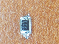
Could i please get some help identifying the circled components in the attached
Thanks
Could i please get some help identifying the circled components in the attached
Thanks
Attachments
-
 170.2 KB Views: 36

")