I don't get a constant amplification on an operational and lower overall amplification

Thread Starter

AndreaM

Joined Apr 19, 2017
11
Hi everyone,

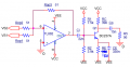
I'm having problem with an aplifier design. It is composed from two stage, the first one is an operational adder and the second one is a common emitter.
I have projected and simulated them to have an amplification of 1 for the operational and an amplification (with no load) of the common emitter of 20.
The specification are Rin = Rout = 50 Ohm, Band from 200 kHz - 1 MHz.

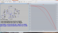
The operational is the integrated TL082 (power suply +\- 6V). The problem is that on the real circuit that I have composed, I dont' get a constant value of amplification on the operational, but it varies with the frequency and by testing different TL082, everyone semms to have a particular trend. The amplification I get is something between 0.5 and 2.5. This influence of cource the final amplification. Futhermore the final amplification is lower than expected, I get something near 10 but I was expection 20. The wave generator is on 50 Ohm (but If I set it on hight impedence, seems to not change nothing), the measure is taken with a tester (hight impedence).

Some one has some explanations? The non stable amplfification of the operational is what bother me most.
 

Attachments

Alec_t

Joined Sep 17, 2013
15,149
I dont' get a constant value of amplification on the operational, but it varies with the frequency
That's because the opamp isn't perfect. Its gain-bandwidth product is only 3MHz and its slew-rate is limited, so gain and phase shift are frequency-dependent.
 

DickCappels

Joined Aug 21, 2008
10,662
To get constant gain you have to have some loop gain.

As Alec_t mentioned in post #3 your opamp does not have a high enough gain-bandwidth to pass your 1 MHz signal in the configuration in which you are using it, let alone have any loop gain left over to give you a constant amplitude, low distortion signal.

You need a faster opamp.

Also, check the plot in the TL08x datasheet that shows maximum output amplitude as a function of load resistance. Unless you only need millivolts you will need an amplifier with more drive capability so it can drive that 50 ohm feedback resistor. To that end, check out bertus' suggestions in posts #2 and #4.
 

Thread Starter

AndreaM

Joined Apr 19, 2017
11
Thanks everyone for your answers.

So I will take a new operational, the LM6171 seems the most powerfull.

Will I need the LT1010 buffer (on input or output of the operational)? (considering the LM6171 and in case of LT1056 where and real needed?).

How can I mathematically demostrate the result that I had, that the bandwith and slew rate of the TL082 are not enough? (and calculate how much be suficent to my application, just to have some number and more clear vision).
 

Thread Starter

AndreaM

Joined Apr 19, 2017
11
Hi everyone,

I bought the LM6171 as you recommended, but however the circuit still has problems.
If I disconnect the BJT and measure the gain of the operational, I get a really good and constant result.
If I disconnect the operational and measure the static point of the BJT I get exactly the working point as projected.
However when I connect both, them do not work properly. The DC working point of the BJT change and the operational does not work. By changing the frequency of the input, on the output of the operational I don't get that change and instead I get a constant value of about 260 kHz, same for the AD that I get a really high and constant value. Seems like a kind of saturation? The opamp is not able to pilot the BJT?
What I have to do? Do I need a buffer?

The scheme is attached on my first post of the topic.
 

Bordodynov

Joined May 20, 2015
3,431
AndreaM.
Than you did not like my scheme. It gives you the result you need. The main thing is that you would use a symmetrical supply voltage.
 

Picbuster

Joined Dec 2, 2013
1,062
Hi everyone,

I'm having problem with an aplifier design. It is composed from two stage, the first one is an operational adder and the second one is a common emitter.
I have projected and simulated them to have an amplification of 1 for the operational and an amplification (with no load) of the common emitter of 20.
The specification are Rin = Rout = 50 Ohm, Band from 200 kHz - 1 MHz.

The operational is the integrated TL082 (power suply +\- 6V). The problem is that on the real circuit that I have composed, I dont' get a constant value of amplification on the operational, but it varies with the frequency and by testing different TL082, everyone semms to have a particular trend. The amplification I get is something between 0.5 and 2.5. This influence of cource the final amplification. Futhermore the final amplification is lower than expected, I get something near 10 but I was expection 20. The wave generator is on 50 Ohm (but If I set it on hight impedence, seems to not change nothing), the measure is taken with a tester (hight impedence).

Some one has some explanations? The non stable amplfification of the operational is what bother me most.
Start to measure at the output of the opamp.
then input of the transistor next emitter and collector.
The cap over the emitter to ground will move the emitter as function of the frequency.
Use the results to define the problem and how to solve it.
( emulators are nice things but the real stuff might differ)

Picbuster
 

Thread Starter

AndreaM

Joined Apr 19, 2017
11
AndreaM.
Than you did not like my scheme. It gives you the result you need. The main thing is that you would use a symmetrical supply voltage.
Thanks for your answer, the fact is that either my schematic should work and on simulator it does, but in the reality it doesn't. So I want to understand why and correct it but without change the dorsal of the two stage because it is for an academic project. However I would deepen your schematics.
And in any case why with the new opamp that should had resolved the problem, it instead does not work?
 

Bordodynov

Joined May 20, 2015
3,431
As the Russian proverb says: The best is the enemy of the good. Perhaps this new operational amplifier is too good. And two cascade non-inverting amplifier shifts the phase a little at the frequency of unity amplification. Try adding a small container with the feedback of the adder. I once had a similar problem. I was engaged in television amplifiers (hobbies). I got the transistors with a maximum generation frequency of 4 GHz. With these transistors, the two-stage amplifier oscillated, with no other. I reduced the current of the transistor. The oscillation ceased with a total gain equal to one. Perhaps my scheme is more stable.
 

Audioguru

Joined Dec 20, 2007
11,248
You are using an opamp that has a very high speed. Then the circuit layout is important. If you use it without supply bypass capacitors close to it or build the circuit on a solderless breadboard that has stray capacitance between all the rows of contacts and wires all over the place then it will oscillate as yours does.
 
Top