 Facebook
 Google
 GitHub
 Linkedin
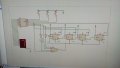
Hi again sir,Here's a circuit that uses 4 positive-edge JK flip flops and an AND gate to output 9 unique sequential states. The AND gate provides the reset logic to reset the flip-flops when the counter reaches 1001 (10 in binary). Next comes the decoder logic to light the relevant segments but you mentioned you know how to do that.
Using this circuit as a reference, can you figure out how to design a truth table and state diagram including the clock, reset and AND gate?
View attachment 338611
Click this link to launch the simulator.
https://tinyurl.com/2ah4s8nz
I have already create simulation a 4-bit up-counter using JK with proteus.
Here is the simulation jpg
Thanks again
Attachments
-
 164.4 KB Views: 5


