I am not satisfied with my headphones amplifire.

Thread Starter

Kshishtoff

Joined Dec 2, 2017
12
Hi everybody :)
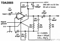
I made an headphone amplifire. I used this schematic. The creator of this schematic promised high quality sound, distortions about 0,005 %, i don't remember exactly, frequency response from 14 Hz to 30 kHz and all that.
I don't understand how it can be truth. The datasheet contains another information about frequency response (40-15 000 Hz) and distortion level (about 0,15 %). Can you explain me divergence of the creator and datasheet?
And one more. This amplifier gives few bass in comparison even to inegral PC souncard. And bass isn't enough deep. But its output signal level is more than enough, so I installed an 39 Ohm resistors in series with its output.
How can I increase bass level?
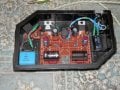
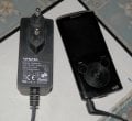
Signal source and power supply you can see on attached photo.
English isn't my native language. I learn it myself. For this reason I ask you to point my mistakes.
Thank you for your attention and answers.
 

Attachments

PeteHL

Joined Dec 17, 2014
596
The specifications given in the datasheet are what I would trust.

It could be that the PC sound-card has bass boosting equalization by default.

You could solve a lack of bass response by line level equalization. But then it is a question of what is the correct equalization.

-Pete
 

MrSoftware

Joined Oct 29, 2013
2,280
The TDA2003 datasheet indicates that it is down 3db by 40Hz, and down by 3db by 15kHz. I don't think there's anything you can do to get a full range sound out of that amplifier. If you're the audiophile type (I am too) then I would choose another amplifier. You can try a lot of equalization to make up for the drop-off on the amplifier, but in my personal experience the result is not as good as just using a better amplifier. If your music has really deep notes, then look for something linear down to 20Hz if you can find it, and up to 20kHz on the high end. You did a nice neat job with the layout though. :)
 

PeteHL

Joined Dec 17, 2014
596
A fairly easy fix for the amplifier you built would be a shelved passive first order low-pass filter with a cut-off frequency of 40 Hz between the line level signal source and your headphone amplifier. In the stop band this would attenuate the signals of frequency greater than 40 Hz by -6 dB. This attenuation should not be a problem as you say that the headphone amp has more power than you need.

If this doesn't help, then maybe you do need some other amp with lower frequency response.

-Pete
 
Last edited:

wayneh

Joined Sep 9, 2010
18,181
Your complaint is with the low end. I wouldn't worry about the high end because I doubt you can hear as high as you think you might. I can't hear much of anything above 11 kHz, but that it age-related and your result may be different. But it's unlikely you can tell any difference between, say, 15kHz and 20kHz. Don't worry about a specification that doesn't actually matter.

You might benefit from using a signal generating app on your smartphone to map out what you can hear and what your amp is not delivering. The app delivers a consistent wave amplitude, making it much easier to challenge the amp with different frequencies than trying to use music. I have used this approach to test different headphones.

I don't see how you can solve the low-end problem without a different chip, as others have noted.
 

Thread Starter

Kshishtoff

Joined Dec 2, 2017
12
I don't think there's anything you can do to get a full range sound out of that amplifier.
I agree with you. I watched the datasheet the other day and i believe it. I've made this amp because of very good mentions on another inet forum. That scheme was higly commended, but it has no any qualities except its simplicity, low price and loudness. IMHO.
You did a nice neat job
No, that job is awful. I had doubts about that scheme and because of it didn't etch PCB.
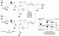
I want to make another headamp based on one voltage-repeater-connected OP. I shall try OP ne5532. That scheme contains few components too, but the creator of that scheme has graduated the MTI and I suppose it will work fine.
It could be that the PC sound-card has bass boosting equalization by default.
And I think it's bad headamp and quite good soundcard :)
Don't worry about a specification that doesn't actually matter.
I don't. But it sounds poor without low frequencies. But loud. But poor... :)
Thanks for all for your attention.
 

Thread Starter

Kshishtoff

Joined Dec 2, 2017
12
Hi JoeJester!
You understand this scheme wrong. TDA2003 is able to give 10 W power only with 14.4 V power supply and 2 Ohm load. And we should use the datasheet scheme.
That scheme has difference from the datasheet's scheme such as decreased gain factor. And I have added two 39 Ohm resistors in series with its output, and I use 9 V power supply. And my headphones has 32 Ohm resistance. Because of it, this headamp will give 10 W and even probably 1 W never.
Probaly that scheme will be good for 600 Omn headphones.
 

AnalogKid

Joined Aug 1, 2013
12,287
The datasheet lists the low frequency response corner *for the test circuit*, not the device. The 2003 will work all the way down to DC. The 3 dB corner frequency probably comes from the 1000 uF output coupling capacitor, which has an impedance of 3.9 ohms at 40 Hz. Increasing the output capacitor to 2200 uF will improve the bass response. However, it also might cause the circuit to break into low frequency oscillation.

The 2003 is an old, reliable part, but it has some problems. All audio power amplifier chips are sensitive to power supply decoupling and signal path routing, but the 2003 is worse than most. Also, it is relatively noisy. No way can it make 0.005% distortion. Your figure in post #1 of 0.15% is much more accurate. If possible, choose another amplifier chip for better performance.

ak
 
Last edited:

Audioguru

Joined Dec 20, 2007
11,248
The NE5532 is also an old IC but it is an opamp, not a power amp. Its minimum load is 600 ohms and its datasheet does not say its distortion.
 

Thread Starter

Kshishtoff

Joined Dec 2, 2017
12
I read several articles written by one guy. He's graduated the MTI and he is good in electronics. He'd made many researches and he says ne5532 is very good for headamp and it is able to work with low-impedance load.
I can give you the links to the articles if you want of course and if it isn't against this forum's rules.
 

Attachments

Audioguru

Joined Dec 20, 2007
11,248
The first circuit from Elliot Sound products uses two NE5532 opamps paralleled per channel with a plus and minus 18V supply for more than 4 times the power of the circuit using single NE5532 opamps.
 

AnalogKid

Joined Aug 1, 2013
12,287
The circuit in the first link, as noted above, cannot source/sink enough current to drive some headphones with adequate volume.
The second link looks like a detailed examination and comparison of several dual opamps, but it is not an actual headphone driver circuit. I don't speak or read Russian, but none of the first five opamps in the first table can drive 16 ohm headphones, making only approx. 40 mW (assuming a 50 mA max output current).There are chips designed specifically to drive headphones and small speakers. On older one is the TDA2222.

ak
 

Attachments

RichardO

Joined May 4, 2013
2,270
The datasheet lists the low frequency response corner *for the test circuit*, not the device. The 2003 will work all the way down to DC. The 3 dB corner frequency probably comes from the 1000 uF output coupling capacitor, which has an impedance of 3.9 ohms at 40 Hz. Increasing the output capacitor to 2200 uF will improve the bass response. However, it also might cause the circuit to break into low frequency oscillation.
If you increase the value of the output capacitor you should also increase the value of the power supply bypass capacitor. This is C4 in your original circuit.
 

AnalogKid

Joined Aug 1, 2013
12,287
Yeah, I didn't work through all of the components. C1 and C2 also might need adjustment to really flatten out the bottom end.

ak
 
Top