How to wire Potentiometer to TDA7492 Bluetooth amplifier board

Thread Starter

brittanysmale

Joined Dec 21, 2017
8
Hi there,

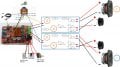
I am looking to build Bluetooth speakers with tweeters and woofers in parallel for each side, through a crossover.
I was wondering if there is a possibility of wiring a potentiometer to control the volume of all four speakers - if so where would they be wired?

I have attached a really rough outline of the the circuit beginning to take shape, as it is only beginning any extra advice about where things are not wired properly would be a great help. Is it possible to connect more than 1 wire to a single spot on the amp board?

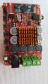
The amp board is TDA7492 - it has the control buttons, but if it is possible I would prefer the volume knob.

I would also like to place a red LED indicator for power and on/off toggle switch.

Any feedback and advice would be appreciated.
Thank you!!
 

Attachments

Audioguru

Joined Dec 20, 2007
11,248
Your crossover network with a single capacitor and a single inductor is too simple. The woofer will still shriek high frequencies and the tweeter will be blown up by low frequencies. Since second-order filters produce a notch or a peak then third-order filters should be used. How will you adjust the levels between the woofer and the tweeter so that they match? Most two-way speakers have a tweeter level control.
 

Thread Starter

brittanysmale

Joined Dec 21, 2017
8
Your crossover network with a single capacitor and a single inductor is too simple. The woofer will still shriek high frequencies and the tweeter will be blown up by low frequencies. Since second-order filters produce a notch or a peak then third-order filters should be used. How will you adjust the levels between the woofer and the tweeter so that they match? Most two-way speakers have a tweeter level control.

Thanks for getting back to me. The crossover I will use is a second order, two-way crossover. I just have not drawn it properly in the diagram yet.

So you suggest adding two volume pots - one for the tweeters and one for the woofers? Would they still wire into the same position on the amp board and then into the positive side of each speaker?

I was wondering if you could wire in into each crossover (left hand side of diagram), would that then be able to control both woofer and tweeter for one side?

Thanks!
 

Thread Starter

brittanysmale

Joined Dec 21, 2017
8
The datasheet is here..

http://www.st.com/en/audio-ics/tda7492.html

Page 22,,
The pins ,30,31 are the volume gain setting, if you tie them to ground supply it sets the gain to minimum, or to 3.3V positive for maximum gain, you can put a Dual gang voume control on the input signal.

Thanks for getting back to me, Dave.
I am very new to electronics, so apologies for my lack of understanding.

Are you saying to wire the Dual Gang pot to the gain settings and then into the input of the speakers?
Where on the Amp board are the gain pins? I can see holes in the board for "+5V and GND" and "L IN, GND, R IN" - but otherwise, not sure which are the others.
 

Dodgydave

Joined Jun 22, 2012
11,395
Looks like your pcb has the gain settings in Dip switches, the volume control will have to be wired at the input signal side.
 

Thread Starter

brittanysmale

Joined Dec 21, 2017
8
Looks like your pcb has the gain settings in Dip switches, the volume control will have to be wired at the input signal side.
Ah yes, that makes sense.

So the input side, is that the "L IN, GND, R IN" holes?
Where would I then wire for the audio source? Can it wire into each crossover (left hand side of diagram), would that then be able to control both woofer and tweeter for one side? Or does there need to be separate control for tweeters and for woofers?

Thanks for your help!
 

Dodgydave

Joined Jun 22, 2012
11,395
Yes, you will need to feed your input to a Dual Gang potentiometer like the diagram below, that way both L/R channels will be controlled, use a 10 to 100K control.


image_37885.jpg
 

Audioguru

Joined Dec 20, 2007
11,248
You are using a simple passive crossover that connects between the outputs of the amplifiers and the speakers. An active crossover using opamps would connect at the input of the amplifier.
The tweeter datasheet would say its recommended crossover frequency.

As I said, a second-order crossover with the woofer and tweeter wired in phase produces a cancellation notch at the crossover frequency. If the phase of the woofer or the tweeter is reversed then the re is a boost of +3dB at the crossover frequency. A third-order crossover does not have these problems. Here is a graph showing the problems with a second-order crossover:
 

Attachments

Thread Starter

brittanysmale

Joined Dec 21, 2017
8
Yes, you will need to feed your input to a Dual Gang potentiometer like the diagram below, that way both L/R channels will be controlled, use a 10 to 100K control.


View attachment 142979
Okay great, I was thinking a 10K Log pot - I have attached an updated diagram with where I believe the wiring should go.
Can you confirm if I have understood correctly?
Thanks again!!
 

Attachments

Dodgydave

Joined Jun 22, 2012
11,395
No, the green terminals are your speaker outputs, the wipers are correct, the Audio input goes to the potentiometer End terminals.
 

Thread Starter

brittanysmale

Joined Dec 21, 2017
8
No, the green terminals are your speaker outputs, the wipers are correct, the Audio input goes to the potentiometer End terminals.
Ah, yes. Thanks.

So I am looking for Pin 22 and 32 of that data sheet?
I've just got to locate them on the board now.

Thanks for your time, you've been very helpful.
 

Thread Starter

brittanysmale

Joined Dec 21, 2017
8
Your speakers appear to be very small and the crossovers have many resistors. Will they work together?
These are the speakers I was going to use:
Tweeters: https://www.parts-express.com/pedocs/specs/275-035-dayton-audio-nd20fb-4-specifications-46117.pdf
Woofers: https://www.parts-express.com/pedocs/specs/264-1062--tymphany-tc9fd18-08-spec-sheet.pdf

I designed the crossover in the Passive Crossover Designer program. I wanted to go with second order crossover for ease rather than going too big - are the extra resistors needed? The speakers have differing sensitivities so was hoping the resistors was able to even that out.

Thanks!
 

Audioguru

Joined Dec 20, 2007
11,248
They are little speakers. The 4 ohm 15W tweeter has a nice flat frequency response but is fairly low power.
The 8 ohm 30W midrange has a nice flat midrange frequency response but produces no bass and is much less sensitive than the tweeter.

The speaker system will probably sound boomy (one note upper bass like a bongo drum) and will need its tweeters to be attenuated.
 

Thread Starter

brittanysmale

Joined Dec 21, 2017
8
They are little speakers. The 4 ohm 15W tweeter has a nice flat frequency response but is fairly low power.
The 8 ohm 30W midrange has a nice flat midrange frequency response but produces no bass and is much less sensitive than the tweeter.

The speaker system will probably sound boomy (one note upper bass like a bongo drum) and will need its tweeters to be attenuated.
It was never going to be a super powerful speaker, just a little DIY project. For just a living room, Bluetooth speaker - do you think this will be problematic in the current wiring diagram I have? Do you have any simple remedies for the current set up?

Sorry I am very new to both electronics and audio, so feedback is appreciated.

Thanks again!
 

Audioguru

Joined Dec 20, 2007
11,248
My son gave me a Aukey Bluetooth stereo and rechargeable speaker as a birthday gift.
It is really small with two 1.5" midrange/tweeter speakers and one 3" x 1.5" oval woofer.
It is loud enough for a living room but its bass is weak. Bose makes a similar Bluetooth stereo and rechargeable speaker that sells for $200.00 and it sounds amazing for its small size.

The Chinese amplifier modules you have are claimed to produce 50 Watts per channel that will destroy your lower rated speakers unless you power the amplifier with a voltage that limits its power to 30W per channel into 8 ohms. ST Micro's datasheet shows that a 24VDC power supply limits the power.
 

Attachments

quimbo_1

Joined Mar 25, 2018
1
Ah, yes. Thanks.

So I am looking for Pin 22 and 32 of that data sheet?
I've just got to locate them on the board now.

Thanks for your time, you've been very helpful.

For us other ones who are new to the audio electronics and how to wire a Potentiometer to a bluetooth amplifer board, could you put a diagram up of the proper wiring.
 

Audioguru

Joined Dec 20, 2007
11,248
You would need the schematic of the Bluetooth amplifier board to see what to cut or remove and how to connect normal volume controls. Maybe the 8-pins IC inline with the pushbuttons is what controls the volume now. Look at its part number and find its datasheet.
 
Top