How to use a capacitor to keep a relay energised for longer?

Thread Starter

perky416

Joined May 5, 2017
16
Hi Guys,

I have an infrared alarm beam that when broken it sends a signal to the alarm control panel. When walking past the beam you can hear the relay click and then reset. If you stand in front of the beam the relay clicks but doesn't reset until you move out of the way.

Walking past the beam quickly doesn't trigger the alarm, when measuring the signal outputs with the multimeter you get a quick signal on/off as the relay trips and resets. You have to walk past the beam slowly or stand in front of it to get it to trigger. My thinking is that the quick on/off signal is too fast for the alarm panel to detect. This was later confirmed when I put a capacitor across the signal wires from the sensor to the alarm. I had to stand in front of it for considerably longer to trip the alarm.

I have been thinking of ways to keep the signal applied for longer. I read an older post on this website which stated that you can use a capacitor across the relay to keep it energised for longer.

I just wanted to double check, would this capacitor need to be placed across the coil on the relay? The relay is a HK4100f for reference purposes.

Many Thanks
 

AlbertHall

Joined Jun 4, 2014
12,640
would this capacitor need to be placed across the coil on the relay?
In principle, yes, this would work. The problem is that we don't know the circuitry that is driving the relay. A capacitor across the relay coil will draw a large current surge when the relay is being energised. This surge of current may damage the driving circuitry or cause a drop in the supply voltage which will upset the circuit in other ways.
 

drc_567

Joined Dec 29, 2008
1,156
What is the distance between the sensor and the control panel?

Sometimes long lengths of wire can have signal distortions due to distributed inductance or capacitance.

So, as an experiment, try using a heavier gage wire as the connection between the sensor and the panel.
 

MrSoftware

Joined Oct 29, 2013
2,273
I understand what you're saying; if someone walks through the beam too quickly, the beam does detect it but the signal to the alarm is not long enough for the alarm to recognize the signal. So you need a way for the alarm to receive a relatively long signal, even if the beam is only broken very quickly.

Maybe you can logically OR a 1-shot timer with the output from the beam. Set the timer for say 1 second. Now if the beam is broken for only 1/4 second, the alarm still receives a 1 second signal. But if the beam is broken for 30 seconds, the alarm still receives 30 seconds of signal.
 

Thread Starter

perky416

Joined May 5, 2017
16
Thanks for taking the time to get back to me, I will get back to you all one by one...

In principle, yes, this would work. The problem is that we don't know the circuitry that is driving the relay. A capacitor across the relay coil will draw a large current surge when the relay is being energised. This surge of current may damage the driving circuitry or cause a drop in the supply voltage which will upset the circuit in other ways.
Yeah I thought it would be across the coil I just thought it best to double check. The board isn't too complex and only appears to be single layer so I may attempt to throw together a DIY circuit diagram and upload it if that's ok so you guys can take a look? I haven't done circuit design since college so im a bit out of practice.

What is the distance between the sensor and the control panel?
Sometimes long lengths of wire can have signal distortions due to distributed inductance or capacitance.
So, as an experiment, try using a heavier gage wire as the connection between the sensor and the panel.
There is about 15m of wire between the sensor and the panel. I have tried it with 2 types of cable, I tried speaker wire and an insulated 2 core cable which was thicker (the exact gauge escapes me) however unfortunately the result was still the same.

How is the schematic?
I don't have an official circuit diagram to hand however as mentioned above I will attempt to put one together later this evening.

I understand what you're saying; if someone walks through the beam too quickly, the beam does detect it but the signal to the alarm is not long enough for the alarm to recognize the signal. So you need a way for the alarm to receive a relatively long signal, even if the beam is only broken very quickly.

Maybe you can logically OR a 1-shot timer with the output from the beam. Set the timer for say 1 second. Now if the beam is broken for only 1/4 second, the alarm still receives a 1 second signal. But if the beam is broken for 30 seconds, the alarm still receives 30 seconds of signal.
You have hit the nail on the head, the way you describe a 1 shot timer sounds exactly what I need. Please could you elaborate on what id need to achieve this? Please also bear in mind that the free space I have to add extra components is only around 3cm x 4xm x 1cm.

Thanks again.
 

Thread Starter

perky416

Joined May 5, 2017
16
Dave, I did google 1-shot-time and found references to the 555. That link looks great, takes all the hard work out, however I am a little confused as to where to put it in regards to my current circuit. Would the output from the PCB you have just showed me drive the relay in my current circuit? Or would the relay drive this PCB?

Thanks
 

Dodgydave

Joined Jun 22, 2012
11,395
The circuit needs a permanent supply and on power up can be modified to give a trigger for the time selected period, you would need to put your existing relay trigger pulse to start the timer on pin 2, we can show you how.
 

Raygl

Joined Dec 3, 2016
12
I have used a transistor with the base hooked to the capacitor with enough resistance that there was no surge problem.
 

BobaMosfet

Joined Jul 1, 2009
2,211
Yeah, if a darlington can be used instead of a coil, I'd go that way. People forget that coils need charge up and dishcarge time.
 

Thread Starter

perky416

Joined May 5, 2017
16
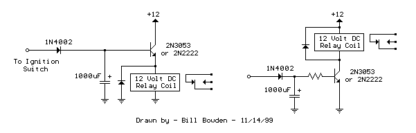
Please take a look at the image attached, i found this circuit when searching google for a relay delay off timer. Would this be ok to do what I am trying to achieve? I could make this small enough to fit into the limited space i have available.

Would it be as simple as drilling the track before the relay coil then adding this circuit in between?

Thanks
 

Thread Starter

perky416

Joined May 5, 2017
16
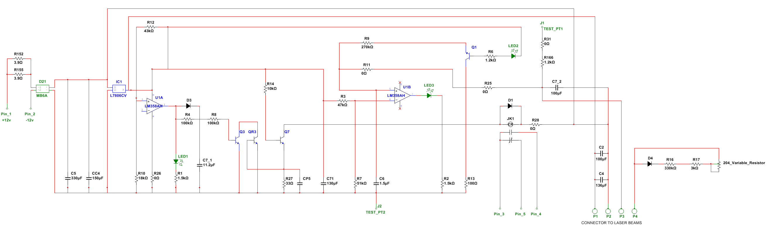
Finally finished putting together the diagram for the board I am working with.
It should be accurate however this was put together yesterday evening and this evening after 11.5 hours shifts at work.
I have tried to make sure all values are actuate however most of the capacitors I had to measure in circuit.
The markings on U1 state LM358 however the closed thing I could find in multisim was the LM358AH.
Q3 and QR3 are L6 transistors, Q7 is an S8050 transistor.
Pins 3, 4 and 5 are the signal coming from the alarm panel and then returning when the relay is energised via the breaking of the laser beams. You can choose whether you would like to have the circuit NO or NC.


Thread Starter

perky416

Joined May 5, 2017
16
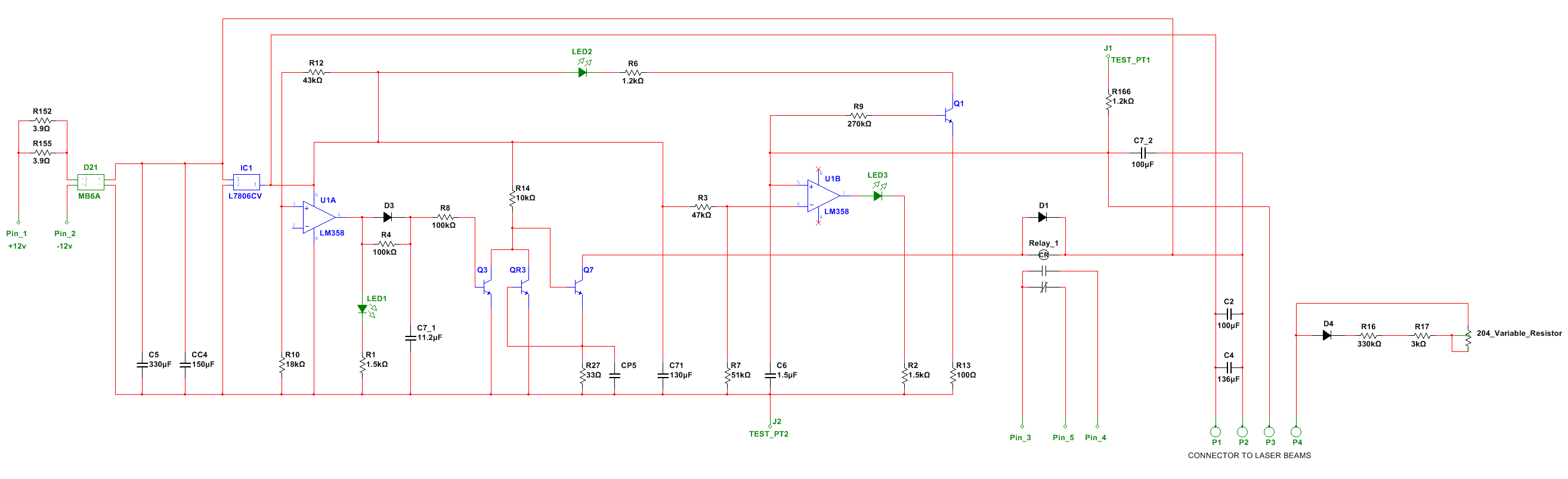
Thanks for pointing that out...will get there in the end lol.
New image below.
Q1, QR3 and Q7 are all correct as per the drawing. Please bear in mind I haven't designed this circuit I am just trying to modify it.
Thanks


Thread Starter

perky416

Joined May 5, 2017
16
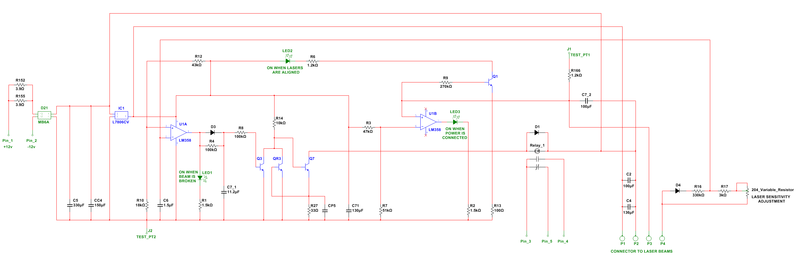
I have found another error in the drawing...this is getting a little embarrassing now. I will upload another one when I am certain there are no more errors.
 
Top