How to turn current off in circuit temporarily when there is current in separate circuit?

Thread Starter

aid545

Joined Jul 10, 2017
11
Hi,


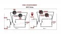
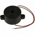
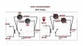
I have a gps unit that sends 12v current to a audio buzzer when car exceeds certain speed.

Sometimes when the radio is on loud and the buzzer warning alarm is drowned out with music from the radio.

Just wondering how I can temporarily turn off the power to the radio/speakers when the gps unit sends 12v current to the buzzer alarm, and restore speaker volume again when the gps unit stops sending current to the buzzer (speed is reduced)?


Thanks

Aid
 

BR-549

Joined Sep 22, 2013
4,928
Have the gps unit send the 12 V current to a SPDT relay. Feed separate buzzer current thru a NO contact pole, and feed radio power thru NC contact pole.
 

Thread Starter

aid545

Joined Jul 10, 2017
11
Thanks for the feedback on this .. only getting around to doing the project now.

Would schematic below be the best way to go about installing the SPDT Relay:

Feed separate buzzer current thru a NO contact pole, and feed SPEAKER power thru NC contact pole (rather then the stereo power as don't want the radio resetting every time the buzzer goes off).

Where would you recommend installing the SPDT on the speaker wires (just after the stereo speaker out connections?).

Thanks
 

Attachments

Dodgydave

Joined Jun 22, 2012
11,284
Your idea is right, but your relay is using a changeover and shorting out the stereo when buzzing , just change your speaker contacts to NC only( remove terminal 2 connection)

Also put the coil in Parallel with the Buzzer..
 

Thread Starter

aid545

Joined Jul 10, 2017
11
I am not too sure if its 12v pulse or a tone .. it gives the buzzer to different noises : 12v continuous beep or non-continuous beep-beep output at 1hz rate.

Buzzer is cheap 85db 12v tone buzzer (like image)
 

Attachments

BobaMosfet

Joined Jul 1, 2009
2,110
I think a PNP transistor would work well for this, with the base pulled to ground with a weak pull-down. The base, via a current-limiting resistor could be attached to the positive lead on the buzzer. The instant the base goes high, the transistor fires and would simply disconnect the speaker.

Just a thought.
 

Thread Starter

aid545

Joined Jul 10, 2017
11
Thanks .. dodgydave should I connect both positive wires from left and right speaker to the one terminal on the SPDT 5 pin relay ? and the negative wires from the speaker bypass the relay and go straight to the speakers? Is that correct way to wire it? And buzzer current thru a NO contact pole.

Thanks
 

Thread Starter

aid545

Joined Jul 10, 2017
11
how would the wiring look with using 5 pin DPDT?

amazon.ca/gp/product/B01MDLX3BW/ref=ox_sc_act_title_2?smid=A3B1HIKEICFRGA&psc=1

or do I need a 7 pin DPDT?


Sorry never used DPDT relay before.

Thanks for your help.
 

shteii01

Joined Feb 19, 2010
4,644
how would the wiring look with using 5 pin DPDT?

amazon.ca/gp/product/B01MDLX3BW/ref=ox_sc_act_title_2?smid=A3B1HIKEICFRGA&psc=1

or do I need a 7 pin DPDT?


Sorry never used DPDT relay before.

Thanks for your help.
https://www.amazon.ca/gp/product/B01MDLX3BW/ref=ox_sc_act_title_2?smid=A3B1HIKEICFRGA&psc=1

That is not DPDT.
That relay switches one contact. You will need two relays. One for left, one for right.

86 and 85 are coil contacts.
85 is Ground/Negative terminal of battery/0 Volts
86 goes to the controller that activates the relay.

87a and 30 are connected together (Normally Closed, NC) when the coil is unpowered, 86 has no voltage on it.
When controller applies 12 volts on 86, the coil will be powered and connection between 87a and 30 will be broken, and the current will be unable to flow.

Since you need two relays activated by the same signal, you need to connect 86 of relay 1 and 86 of relay 2 to the same signal. That way controller applies 12 volts to coil of relay 1 and to coil of relay 2 at the same time.
 
Top