 Facebook
 Google
 GitHub
 Linkedin
Hello!
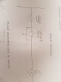
Would anyone know how to transform this circuit into a boolean gate diagram and equation?
Thanks
Would anyone know how to transform this circuit into a boolean gate diagram and equation?
Thanks
Attachments
-
 185.2 KB Views: 15


