How to refine my attentuator

Thread Starter

tsmspace

Joined Mar 16, 2026
133
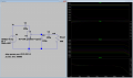
So, my attenuator is basically a 50k potentiometer and 3 caps at present. It seems to work.

It is a 100uf electrolytic in series with input and output to couple the signal, and a 100pf cap between the output of the potentiometer and ground.

I guess I have no idea how to calculate the impedance, the bandpass, and to understand why it seems to add noise. It's definitely true, I have a lot of wires everywhere, so there will be plenty of noise picked up by the wires. There is no shielding anywhere, and I am in a noisy environment.

I would like to tune it to operate best from audio range to 1.6mhz , and this is because I am able to make this signal with the signal generator I plan to use with it. The most use will be audio range, but I may use it above 1mhz also, idk, if for nothing else than to see it work.Untitled.png
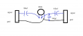
edit:;;; basically, it looks like if I increase the size of the capacitor, I can lower the frequency of the lopass filter, so when I put too much attenuation, the resistance that applies to the low pass filter drops too much, and the cutoff frequency of the lopass filter goes way up, allowing lots of high frequency noise onto the line. I wonder if my best approach is to use female pins to let me just change the capacitor by inserting one into the pins.
 
Last edited:

Pyrex

Joined Feb 16, 2022
513
Yeah, it works, but not very well. First – why is a 100pF capacitor needed? When a high-frequency signal, around 100kHz and above, is applied, this capacitor will strongly attenuate the signal, and the higher the frequency, the more it will.
Secondly, electrolytic capacitors work poorly with high-frequency signals, they should be bypassed with 100nF capacitors.
Why choose 100uF capacitors? For audio frequencies, 4.7uF or smaller capacitors would be enough.
Shielding is necessary, it’s no wonder that noise appears.
And with such a high frequency, like 1.6 MHz, a general purpose potentiometer won't work well because its internal capacitance will start to play. For the attenuator to work well at high frequency, a multi-position switch with several resistor and capacitor combinations is usually used, and this is done to smooth out the frequency response.
 

MisterBill2

Joined Jan 23, 2018
27,741
First, post#1 DOES NOT mention the signal frequency, nor the amplitude, nor the source impeadence. SO any answer is at best a general statement that may not easily be applicable.
 
Last edited:

Thread Starter

tsmspace

Joined Mar 16, 2026
133
First, post#1 DOES NOT mention the signal frequency, nor the amplitude, nor the source impeadance. SO any answer is at best a general statement that may not easily be applicable.
well,, it's an xr2206 kit , which means it will have a frequency range from 1hz-ish to 2mhz in the best cases, although I have seen reasonably good low amplitude sync output at about 1.6mhz. Really it works best below 500khz imo.

this design of xr2206 kit is powered on +6,-6 , I typically end up wanting to use a signal that is around 4vpp, as it is the cleanest when I look at it on the scope compared to lower amplitude, although i can make like a 9vpp signal.

the xr2206 datasheet appeared to show no impedance data correlating to output, but I suppose that's because it is probably dynamic with frequency and amplitude of output.

Yeah, it works, but not very well. First – why is a 100pF capacitor needed? When a high-frequency signal, around 100kHz and above, is applied, this capacitor will strongly attenuate the signal, and the higher the frequency, the more it will.
Secondly, electrolytic capacitors work poorly with high-frequency signals, they should be bypassed with 100nF capacitors.
Why choose 100uF capacitors? For audio frequencies, 4.7uF or smaller capacitors would be enough.
Shielding is necessary, it’s no wonder that noise appears.
And with such a high frequency, like 1.6 MHz, a general purpose potentiometer won't work well because its internal capacitance will start to play. For the attenuator to work well at high frequency, a multi-position switch with several resistor and capacitor combinations is usually used, and this is done to smooth out the frequency response.
well I suppose I put it there to try and filter high frequency noise. I want the potentiometer because i want the fine tuning without a million steps, it's not that big of a deal I'm not exactly designing a radar.
 

Irving

Joined Jan 30, 2016
5,184
The data sheet says its 600ohm:
1783345084586.png

You can estimate the xr2206 output impedance by attaching the pot across the output, wiper to out, one end to ground, Start with the highest resistance, monitor output volts while reducing resistance. When output volts drop by 50% the pot's resistance is roughly equal to the output impedance. Try for various frequencies/amplitudes to get a feel how it changes. It might be quite low so you may not get a sensible result doing it with a 50k pot, in which case use a set of small value resistors (10ohm to 1Kohm) and measure the change in output volts; from that you can work out the output impedance indirectly.

You might have a play with LTSpice - free download here to experiment with component values. Here you can see the effect of the pot on the output of the xr2206, and the HF rolloff due to the 100p capacitor. I've assumed a 600ohm load on the whole circuit.

1783347004229.png
 
Top