How to optimize solar powered joule thief

Thread Starter

surveyranger

Joined Nov 5, 2020
5
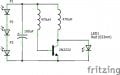
I cobbled together a solar powered joule thief circuit from through hole components I had (1st picture). It consists of 3 x BPW34 photodiodes, 100uF electrolytic capacitor, 2 x 470uH axial inductors, 2n2222, and a red LED. The open voltage of a BPW34 is .4V, and the loaded voltage of all 3 combined under the same conditions is .463V (as measured with a Fluke 27 DMM). The intent is to use this for an indoor project.
The joule thief works in the sense that the LED blinks in low light, and is dimly lit in bright light. I would like for the LED to be brighter. I experimented with switching out components. I found that the circuit will not work with a capacitance below 47uF, and blinks slower as the capacitance gets larger. The axial inductors looked like they performed the same at 220uH, 330uH, 470uH, and 680uH. However, the base and collector inductors had to be the same size.
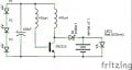
Also, I tried adding another capacitor in parallel with the LED, but that caused the LED not to light up at all after I left the circuit in bright light for an hour. Then, I added a 1.2V 80mAh NiMH battery in parallel with the LED along with a Schottky diode to prevent battery discharge back into the circuit (2nd picture). The LED did not light up either in that configuration after I let it sit overnight.

Any ideas how to make the LED brighter using minimal components? I'm trying to keep the footprint small.
 

Attachments

jiggermole

Joined Jul 29, 2016
161
Well a very simple stupid way is to use a green LED. Green appears brighter to the human eye. Not the answer you want I know but they won't let my install ltspice on my work computer.
 

Thread Starter

surveyranger

Joined Nov 5, 2020
5
If they are not like this already, you can try putting the base and collector inductors on the same core.
The axial inductors are discrete components. When they touch each other, the LED does not light up. I have to keep them separated on the breadboard circuit.
 

DickCappels

Joined Aug 21, 2008
10,152
If you have them phased correctly when current goes through the collector winding (when the transistor is on) it will add to the base current, helping the collector current increase. The net effect is that the collector current will be higher and the LED driven harder when the transistor switched off.
 

Thread Starter

surveyranger

Joined Nov 5, 2020
5
If you have them phased correctly when current goes through the collector winding (when the transistor is on) it will add to the base current, helping the collector current increase. The net effect is that the collector current will be higher and the LED driven harder when the transistor switched off.
Thanks for sticking with me on this. I'll switch the inductors around to see if I notice any difference in brightness.
 

Audioguru again

Joined Oct 21, 2019
6,673
A solar garden light costs $1.00 or $2.00 at Walmart. It comes with a fairly bright white LED, A 2V solar panel, a Ni-MH battery cell, a single inductor and an IC that boosts the battery voltage at night and charges the battery in daylight.
I added a Schottky diode in series with a colors-changing LED and a 0.1uf filter capacitor parallel with the LED on most of my many solar garden lights. The value of the inductor sets the LED brightness.
 

Attachments

schmitt trigger

Joined Jul 12, 2010
870
Exactly what Dick Cappels mentioned.
Those are coupled inductors, and should be wound in a common core.

During last year’s pandemic I spent almost a month at home.
I had the time to thoroughly investigate the joule thief and actually typed a write up.
Let me see if I can find it.
 

Thread Starter

surveyranger

Joined Nov 5, 2020
5
A solar garden light costs $1.00 or $2.00 at Walmart. It comes with a fairly bright white LED, A 2V solar panel, a Ni-MH battery cell, a single inductor and an IC that boosts the battery voltage at night and charges the battery in daylight.
I added a Schottky diode in series with a colors-changing LED and a 0.1uf filter capacitor parallel with the LED on most of my many solar garden lights. The value of the inductor sets the LED brightness.
I took apart one of the solar lights before and found the QX5252 IC. Bought a couple, but they don't work the way I want them too. If the voltage from the solar panel is too low, then it triggers the led to turn on.
 

Thread Starter

surveyranger

Joined Nov 5, 2020
5
Exactly what Dick Cappels mentioned.
Those are coupled inductors, and should be wound in a common core.

During last year’s pandemic I spent almost a month at home.
I had the time to thoroughly investigate the joule thief and actually typed a write up.
Let me see if I can find it.
I was trying to avoid a toroid because of the size it occupies, and I understand what DickCappels was saying about the common core.
 

DickCappels

Joined Aug 21, 2008
10,152
About cores,
Rusty Nail Night Light

These blocking oscillator type power supplies work best with ferrite cores, and sometimes they can be hard to locate. Some readers have expressed anxiety over making inductors, and that is understandable since to many, inductors have an aura of mystery about them.

Just to prove that these inductors aren't magic, or even that critical for that matter, I wound one on a rusty nail that I noticed laying beside the road one day while waiting for a tow truck. It is a 2-1/2 inch (6.5 cm) long flooring nail, which serves as the inductor's core.

The wire is a twisted pair of #24 solid copper wire that I pulled from a length of CAT-5 (ethernet) cable, which is similar to the wire used to connect telephones inside buildings. I wound 60 turns of the twisted pair in about three layers around the flooring nail, then I connected the start end of one conductor to the finish end of the other conductor and that made it into a 120 turn center tapped inductor.

I connected it to a 2N2222, a 1K resistor, a 1.5 volt penlight cell, and a white LED. Nothing happened. Then, I put a .0027 uf capacitor across the 1 K resistor (it happened to be on the work bench) and the LED came on. Sometimes you need .001 uf or so. The LED glows nicely and the circuit draws 20 milliamps from the AA cell. The waveform on the oscilloscope looks terrible, but the point is that the circuit oscillated with even this rusty nail, and it boosted the output of the 1.5 volt AA cell to over 3 volts peak to drive the LED.

Those who are familiar with some aspects of coil core selection would quickly point out that the eddy currents would be huge since iron has a low resistance compared to ferrite, or air for that matter, and that there would also likely be other types of large losses. The point here is not that you should run out and buy some flooring nails to make LED lamps, but that this circuit was not "designed", but was thrown together and worked quite readily. If a rusty nail and some telephone wire is enough to light up a white LED, then the inductor is not so critical. So, relax, go buy a ferrite core and get started on your project.

1630154740675.png
(Above) Rust Nail Night Light. This LED power supply was thrown together in a few minutes using scrap parts.
Well, ok the LED itself was not really scrap.

Common Sources for Ferrite Cores

Wolfgang Driehaus from Germany wrote to point out that ferrite cores are used in compact fluorescent lamps, and he further stated that he has had success in making the cores work in this LED power supply circuit. It was only a day after receiving his email that I looked up at the ceiling and saw some lamps that needed replacement. Here is what I found.

1630154817351.png

Some compact florescent lamps from Sylvania had failed in my home. After buying new Philips lamps to replace them, I ventured into the garage to take one of the Sylvania lamps apart. The first problem was getting to the electronics in the base of the lamps. In later correspondence, Wolfgang showed me that the base of the lamp can be pried open and the circuit board removed without having to break any glass. Be careful not to break the glass tubes in the lamp, as they contain mercury, which is toxic.

1630154843957.png

Inside the base of the lamp, as Wolfgang Driehaus, I found three inductors with ferrite cores, as well as a pair of high voltage transistors, a high voltage capacitor, and some other potentially useful components. The inductors were wound on three types of cores, which are a bobbin core (left, covered in heat shrink tubing), a toroid core (center) and an E-E core, (right).

I wanted to confirm the usefulness of the cores for myself, so I removed the existing windings from the bobbin and toroid cores. I cracked the E-E core in several places during the process of separating it from the coilform, so I did not have a chance to try it in the power supply circuit.

On the bobbin core, I wound 50 turns of #32 magnet wire, pulled out a center tap, and then wound another 50 turns. I connected this to a 2N4401, a 330 Ohm base resistor, and a white LED, according to the circuit at the top of this page. When I connected a power supply set to 1.5 volts, the LED lit up brightly. Ok, that is solid confirmation that the bobbin core from this particular Sylvania light works in this application.

On the toroid core, I wound 10 turns of #26 wire wrapping wire, pulled out a center tap, and wound another 10 turns. Connecting it in the same circuit (2N4401, 330 Ohms, white LED) with a 1.5 volt power supply, I saw that the LED lit up, but not as bright as with the bobbin core, but then again, I had only put 20 turns on the toroid.

So now we have a very common source of toroids. Compact florescent lamps are available in places, and as Wolfgang pointed out, they eventually wear out and need replacement.

Another reader pointed out that another source of ferrite cores is the shielding beads used on computer peripheral cables. Those plastic-encased lumps on monitor, keyboard, and some USB cables are actually ferrite cores. If you are about to toss an old keyboard into the recycling bin, why not cut off that ferrite bead first? Christian Daniel of Gernany wrote, noting that the shielding beads are not idea for this kind of use, so you might want to try this last.


Alternative Types of Cores

If you can't find a ferrite core, or even an old rusty nail, all is not lost. You can still make a pretty good white LED power supply by using a non-magnetic core. It sounds like an oxymoron, but a nonmagetic core has little effect on the magnetic flux from the windings, and therefore does not interact strongly with the circuit -it is there mainly to provide mechanical support. Two experimenters have provided reports of their experiences with nonmagnetic cores, each with its unique attributes.

The wood core inductor (no kidding)

Bill Levan in the United States came up with a wood core inductor. His circuit powers a white LED from a 1.2 volt 700 milliamper-hour cell. Mr. Levan reports that he used the rusty nail night light circuit, but found that he did not need the capacitor across the resistor.

1630154908547.png

The coin is a United States quarter dollar, 2.54 cm (1 inch) in diameter, for size comparison.
Take a close look at the LED - it really is on.

If the wood is dry, the material itself will not have a significant effect on circuit operation. Wood that has a lot of water in it might lower the efficiency of the circuit a little bit, but most likely, you would not be able to tell.

1630154943974.png

Mr. Levan's wood core is 5.08 cm x 12.7 mm x3.18 mm (2 inches x 1/2 inch x 1/8 inch). The wire is 30 gauge solid conductor insulated wire wrapping wire, Radio Shack #278-501. (Remember Radio Shack?)

Wind 100 turns, pull out the center tap, then wind 100 turns more. In total, there are 200 turns.

Air Core Inductor

Antonis Chaniotis in Greece converted his children's incandescent night light to use two LEDs in parallel, and increased battery life from one night to about 30 hours of light over three nights.

1630154986966.png


The LEDs, while emitting green light, are electrically similar to the white LEDs in the other circuits because, similar to most white LEDs, the die emits ultraviolet light, which excites green phosphors. Of course in the white LEDs, the phosphors emit white light. The large capacitor in the picture is 100 uf 25 volts, connected from the emitter of the transistor to the tap on the inductor, and it acts as a bypass capacitor to insure that the circuit sees a low impedance from the battery and switch. It may increase efficiency, especially as the batteries runs down and the batteries' internal resistance increases.

The base resistor is 10k, and the batteries is made of two 1.2 volt rechargeable cells in series.

Mr. Chaniotis' analyzed the circuit with SPICE and confirmed his findings by experiment. Interestingly, his analysis showed that for his circuit the optimum location for the tap is not in the center.

The coil is a total of 35 turns 80 mm (3.2 inches) in diameter with no core. Start by winding 14 turns, the start is the collector winding. Pull out the tap for the battery connection, and then wind an additional 21 turns for the base winding.

Once, I made a similar coil for a different kind of application. I used a plastic food storage container from the kitchen as a coil form, then after winding, carefully slipped the coil off the container and held the wires together with tape. From the photograph, Mr. Chaniotis wrapped some wire around the bundle to hold it together.

A core should not be a problem. It is how you wind the windings and have them phases with respect to one-another.
 
I think it would be interesting if people mentioned some specifications about their ad hoc experiments - like report at least the microHenry values of their coils. I find it odd that everywhere there are specific numbers for resistors, capacitors and the like but inductors are: I wound n turns on this thing I found.:)
And there are more variables that would be harder to measure for most, Quality factor, (Q), Saturation Current, DC Resistance. Maybe not important in this design but still would be interesting if values were posted just to compare notes.
 

DickCappels

Joined Aug 21, 2008
10,152
Few or none of the people doing these imaginative experiments had instruments more sophisticated a digital voltmeter.

The point of the collection is to show that for something as simple as a blocking oscillator anxiety over core material can be a detriment to progress.
 

Audioguru again

Joined Oct 21, 2019
6,673
My solar garden LED lights are powered from one AAA Ni-MH battery cell. The voltage boosting circuit is a QX5252F 4-pins IC
that operates at a few hundred kHz with a little 82uH inductor that looks like a 1/4W resistor.
The inductance from 33uH for very bright to 330uH for not bright sets the peak LED current. I add a series Schottky rectifier diode feeding a 0.1uF ceramic smoothing capacitor to power a colors changing LED.
 
Top