How to make stable RF Power Amplifier output

Thread Starter

Mike2526

Joined Nov 10, 2020
86
Dear all,

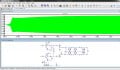
hope you are doing great. Here, I am with a question that I have designed a power amplifier that works at the frequency of 7MHZ ~ 9MHZ. The required output voltages are about 15~18 Vpp. At startup I can get 24Vpp then within a short time it declined to only few mV. So, i need an expert's help who can fix this problem and also suggest me what is issue. I shall be greatly thankful to him/her in this regard (I can share the circuit as well). the screenshot is attached for reference.

1727276100225.png

1727276265778.png
 

Papabravo

Joined Feb 24, 2006
22,058
Excuse me for livin', but that output does not appear to be unstable as that term is usually understood. What is the input and where is your schematic diagram?!! Do you expect magical answers from pitifully insufficient information?
 

MisterBill2

Joined Jan 23, 2018
27,159
Just as "P"states, a dropping output in an RF amplifier is usually not called instability.
Now for the questions: What is the load impedance? That matters.
What is the gain?? either in dB or in volts out per volt in.
What class of operation/ allowable distortion level??
What is the operating power source?? battery, mains, generator, or (other)??
Without that information the best you can expect is random guesses. And really, that information is required for any reasonable design effort.
 

Thread Starter

Mike2526

Joined Nov 10, 2020
86
Excuse me for livin', but that output does not appear to be unstable as that term is usually understood. What is the input and where is your schematic diagram?!! Do you expect magical answers from pitifully insufficient information?

Thank you for your prompt reply. I apologize for the confusion in my previous message. I am facing a voltage drop issue, with my output dropping from 24Vpp to just a few mVpp. My goal is to achieve at least 15Vpp. I am using an IRF510 MOSFET with a 5Vpp square wave input at 7.7MHz-8.7MHz, applied to both VP1 and VP2(which are of the same magnitude but opposite in polarity). Vcc is 5V and VDD is 24Vdc. I have attached a schematic diagram of my current setup for your review and analysis. I would greatly appreciate your expertise and assistance in troubleshooting this issue. Your guidance would be invaluable in helping me achieve my desired output voltage.

Thank you again for your time and consideration.
 

Attachments

Thread Starter

Mike2526

Joined Nov 10, 2020
86
Just as "P"states, a dropping output in an RF amplifier is usually not called instability.
Now for the questions: What is the load impedance? That matters.
What is the gain?? either in dB or in volts out per volt in.
What class of operation/ allowable distortion level??
What is the operating power source?? battery, mains, generator, or (other)??
Without that information the best you can expect is random guesses. And really, that information is required for any reasonable design effort.

Dear MisterBill2, Thank you for your prompt reply. I apologize for the confusion in my previous message. I am facing a voltage drop issue, with my output dropping from 24Vpp to just a few mVpp. My goal is to achieve at least 15Vpp. I am using an IRF510 MOSFET with a 5Vpp square wave input at 7.7MHz-8.7MHz, applied to both VP1 and VP2(which are of the same magnitude but opposite in polarity). Vcc is 5V and VDD is 24Vdc.

The output impedance is 50ohm. The class of operations is class E (but the class maybe D, EF or any). I have attached a schematic diagram of my current setup for your review and analysis. I would greatly appreciate your expertise and assistance in troubleshooting this issue. Your guidance would be invaluable in helping me achieve my desired output voltage.

Thank you again for your time and consideration.
 

Attachments

Thread Starter

Mike2526

Joined Nov 10, 2020
86

Dear Bordodynov, I just run the simulation on my system and i found the following observation.

1. The output voltages in your screenshot is about 4.2Vpp at 1ms, while at my system its 2.5Vpp at 3.6ms.
2. Voltages are increasing steady. I am afraid after the long-time voltage will be stable or increased steadily.
3. I need at the output about 15Vpp (at least).
4. How can we get the smooth and stable voltages.

anxiously waiting for your further kind suggestions and recommendations.
 

Attachments

Bordodynov

Joined May 20, 2015
3,429
You will have to increase the current through the transistors, and to do this, adjust the divider resistors. I just showed you that there would be no initial outburst. To do this, I added an RC circuit.
 

Thread Starter

Mike2526

Joined Nov 10, 2020
86
That's better!

I suspect that if you get rid of all those traps (parallel LC circuits) in your output, you signal will look nicer.
Dear Sir, i would like to inform that i already did this experiment and found that the results are same. I just shared the schematic with you that works well, the output is smooth now. but the output voltage's magnitude is just 2.5Vpp while i need 15~18Vpp. Waiting for further recommendations.
 

Thread Starter

Mike2526

Joined Nov 10, 2020
86
You will have to increase the current through the transistors, and to do this, adjust the divider resistors. I just showed you that there would be no initial outburst. To do this, I added an RC circuit.
Yes Sir, you are right, there is no initial outburst and i simulated the circuit several times after little modifications. now the output is smooth, but the magnitude is just 2.5Vpp, while i need 15~18Vpp. so, you mean to say i can control the magnitude by adjusting the values of voltage divider circuit (which contain R5 & R6), is it? Anxiously waiting for your next further recommendations.
 

MisterBill2

Joined Jan 23, 2018
27,159
With the output amplitude varying with time as it appears, the most likely cause is heating of the active devices, and possibly even the coils getting warm and increasing resistance.
So I am suspecting that the gate drive to the power mosfets is not adequate. With Vcc at 5 volts that is probable. In the simulator, examination of the drain waveform is simple, so I suggest that as a starting point.
 

Thread Starter

Mike2526

Joined Nov 10, 2020
86
The coil I have used is an RF chock coil that is used for protection of power MOSFET. Do you think if I will make a hardware it will produce a lot of heat which can affect the output stability or magnitude?
 

MisterBill2

Joined Jan 23, 2018
27,159
The heating in the coil will be due the the current, both DC and AC.
Consider that we do not know the diameter of the conductor in the coil, not the resistance, nor the current in the coil, it is not likely that we could make even a poor guess about how much heating there might be. We have one equation and quite a few unknowns.
 
Top