There is one other way to vary a sine-wave amplitude that occurred to me.
If you generate the sine-wave using a modulated PWM signal, then controlling the amplitude of the PWM signal will also vary the amplitude of the filtered sinewave from the PWM signal.
There is one other way to vary a sine-wave amplitude that occurred to me.
If you generate the sine-wave using a modulated PWM signal, then controlling the amplitude of the PWM signal will also vary the amplitude of the filtered sinewave from the PWM signal.
Going back to the first question - and just out of curiosity - what sort of sensor do you have to drive with a sinewave?
If you want to vary the amplitude, try making the Wien bridge using a low-power rail-to-rail op-amp such as Microchip's MCP6051, the oscillator output will increase until it is slightly clipped. If you want to vary the amplitude, vary the power supply. You can use the output of another op-amp as the power supply to the Wien bridge. Unconventional, but effective.
A Wien bridge probably isn't the best oscillator under the circumstances as it takes an age for the amplitude to settle. If the input voltage was changing all over the place, the output wouldn't be able to keep up.
Alternatively, and more conventionally, as you only need two-quadrant multiplication, the LM13700 would work.
The very simple analog multiplier is an analog switch. Use a unity gain buffer both before and after the switch, so that the driving source impedance will be low and the follower input impedance will be high. The oscillator drive voltage should be high enough to operate the switch. This will add two IC devices but no additional resistors or complex math.
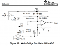
A Jfet is frequently used to limit and control the output level (Auto Gain Control) of a Wien Bridge oscillator. It works by rectifying the output signal into DC that varies the conduction of the Jfet. The circuit prevents the sinewave from clipping.
An external DC control voltage can add or subtract from the control voltage. Here is the Jfet circuit shown by Texas Instruments:
That circuit requires quite a few components, several need to be very specific values, plus also a stable reference voltage. The simple switch circuit is a modern version of the "Chopper" scheme that was widely used in the late sixties, to allow AC amplification of DC voltages. At that time it was a mature technology, and it still works well. But it is now seldom cost effective.
The very simple analog multiplier is an analog switch. Use a unity gain buffer both before and after the switch, so that the driving source impedance will be low and the follower input impedance will be high. The oscillator drive voltage should be high enough to operate the switch. This will add two IC devices but no additional resistors or complex math.
Going back to the first question - and just out of curiosity - what sort of sensor do you have to drive with a sinewave?
If you want to vary the amplitude, try making the Wien bridge using a low-power rail-to-rail op-amp such as Microchip's MCP6051, the oscillator output will increase until it is slightly clipped. If you want to vary the amplitude, vary the power supply. You can use the output of another op-amp as the power supply to the Wien bridge. Unconventional, but effective.
A Wien bridge probably isn't the best oscillator under the circumstances as it takes an age for the amplitude to settle. If the input voltage was changing all over the place, the output wouldn't be able to keep up.
Alternatively, and more conventionally, as you only need two-quadrant multiplication, the LM13700 would work.
Well, it is a self-made tactile sensor.
Yes, varying the supply is good. However, the control voltage sometimes would be smaller than the minimum supply voltage.
The "simple as possible" scheme is functionally a multiplier where one of the signals oscillates between zero and one. That is the switching control signal from an oscillator. The other signal is the analog voltage from whatever it is. That is the signal that gets switched off and on, converting it to AC. The two unity gain amplifiers are to feed the switch input from a very low impedance and then isolate the switch output from whatever the signal is sent to. No resistors need be part of the circuit, and the capacitors will be power feed bypass capacitors.. There is a lot of application information about analog switches available, as well as unity gain buffer amplifiers.
It does not seem like you really need a sine wave oscillator, especially if you use an analog switching IC. A square wave oscillator will be better for that appication.
BUT you will need to select both components to be able to work with the supply voltages in your system. THAT PART is important.
AND, it apears to be an ANALOG sensor with a variable resistance output.
Indeed the type of sensor matters, because some sensors couple in whatever outside voltage is at the touch point, which is usually including some cacitivly couples mains frequency component.

 Facebook
 Google
 GitHub
 Linkedin