how to interface Relay to microcontroller

Thread Starter

abhimanyu143

Joined Aug 25, 2014
211
Hello
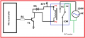
I have fear in my mind, first time I am going to use relay in my project. I have done all work under 12 v dc. now I am trying to connect relay to mains power. that's why I need suggestion I don’t understand how to interface relay to 8051 and AC motor
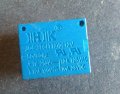
relay has 5 pins
1. which Pins of relay connect to port of microcontroller (8051) ?
2. which Pins of relay connect to mains power ?
3. which pins of relay connect to AC motor ?
4. look at image. It is suitable for AC motor ?
 

Attachments

MikeML

Joined Oct 2, 2009
5,444
Your picture does not load properly, and needs to be reduced in size before posting...

What are the specs on the motor (Locked rotor current, running current, HP)?

How do you propose to drive a 12V relay from a 5V port? NPN? NFET?
 

Thread Starter

abhimanyu143

Joined Aug 25, 2014
211
Your picture does not load properly, and needs to be reduced in size before posting...

What are the specs on the motor (Locked rotor current, running current, HP)?

How do you propose to drive a 12V relay from a 5V port? NPN? NFET?
What are the specs on the motor
specification AC motor
Power rating : 0.37kW/0.5 Hp
Voltage range : 180 to 240 Volts

How do you propose to drive a 12V relay from a 5V port? NPN? NFET?
I have 4 k resistor and NPN transistor
 

Attachments

Last edited:

MaxHeadRoom

Joined Jul 18, 2013
28,617
The circuit is wrong for your configuration the low voltage DC common and the AC side should not be connected, IOW galvanically isolated.
The circuit show a diag. for a motor and control powered off the same supply.
The AC power goes to one N.O. contact the motor the other, the neutral goes direct to the motor.
If you are asking these very simple basic questions you may want to brush up on your basic electronics first.
Max.
 

Thread Starter

abhimanyu143

Joined Aug 25, 2014
211
The circuit is wrong for your configuration the low voltage DC common and the AC side should not be connected, IOW galvanically isolated.
The circuit show a diag. for a motor and control powered off the same supply.
The AC power goes to one N.O. contact the motor the other, the neutral goes direct to the motor.
If you are asking these very simple basic questions you may want to brush up on your basic electronics first.
Max.
Is it right connection ?
 

Attachments

MikeML

Joined Oct 2, 2009
5,444
Could be a little misleading, not to say dangerous using green for AC power, that is the colour code for GND, should be white, neutral.
Especially if the motor has a green gnd wire already attached.;)
Max.
Tell the TS (OP). He chose the wire colors. I think he is in a part of the world that does not use green...
 

Thread Starter

abhimanyu143

Joined Aug 25, 2014
211
relay.png
look at image , when I do same connection on breadboard. AC motor does not turn ON/off
do you see any fault in connection ?
 
Last edited:

John P

Joined Oct 14, 2008
2,025
It says 7A at 240V on the case, and 1/2HP at 240V is less than 2A. Anyway, a solid-state relay would be silent and could run directly off 5V. He should be using that instead.
 

Thread Starter

abhimanyu143

Joined Aug 25, 2014
211
I have changed idea , I am planning to use another motor
voltage 165-250 V
Power Consumption 20 W
Output Power 1100 l/h

I have specification of motor and relay. how to know that relay is suitable for above specification?
 

MikeML

Joined Oct 2, 2009
5,444
It says 7A at 240V on the case, and 1/2HP at 240V is less than 2A. Anyway, a solid-state relay would be silent and could run directly off 5V. He should be using that instead.
I saw what is printed on the top of the relay; it still doesn't look up to the job to me...
 

vead

Joined Nov 24, 2011
629
Hello again
actually I don't understand the wiring connection to power supply and lamp. there are two wires of supply and lamp, I don't understand how to connect them with relay wires. look the connection in image. If the all connections are correct than I will go for program
relay with lamp.jpg
 

vead

Joined Nov 24, 2011
629
It doesn't get much clearer than that??
You may also want to look at a 2n7000 'Fetlington' in place of the BC547.
Max.
ok its just diagram to show the wire connections. I am not using BC547. If you will see the my last post. I am asking about lamp and supply connection. Is it right connection ?
 
Top