How to get full duty cycle range from Hall effect / 339 PWM

Thread Starter

dlatch

Joined May 15, 2016
91
I built this circuit. It works great but, only yields half of the duty cycle range due to the Hall chip having a 50% quiescent output.

How can I get the full duty cycle range? (0-100%) The Hall chip is marked 1216 001H. It is a 5 volt magnet meter type chip.

thank you
 

Attachments

crutschow

Joined Mar 14, 2008
38,578
What is the output voltage range of the Hall chip?
You need to amplify (and offset if necessary) the Hall chip output so that it goes from about 0.8V to 4.2V of 0% to 100% duty-cycle.

Alternately you could change the sawtooth output so that it goes between the low and high voltage range of the Hall chip.
 

Thread Starter

dlatch

Joined May 15, 2016
91
The Hall output powers up to 2.5V. One magnet pushes it up to 5, the other pulls it down to 0. So it gives 50% to full duty cycle or the opposite with the other magnet polarity. I can only use one magnet polarity.
 

Thread Starter

dlatch

Joined May 15, 2016
91
I don't know how to use a simulator...not yet. don't wait for it.

I am probably using the wrong Hall sensor. This one was recommended to make a magnet meter. I built that and it works fine for ceramic magnets allowing you to measure both N and S. It is typical of the "ratiometric" sensors. They have a quiescent output of 50% vcc.

I have been searching for a Hall sensor that simply swings from basically 0 to basically vcc but I have not found one.

Perhaps I will post a video showing the operation of it on an Oscilloscope
 

Thread Starter

dlatch

Joined May 15, 2016
91
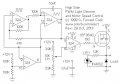
That is an image found elsewhere on these forums. I used it to build the circuit. Too bad the Hall sensor is not specified.

I believe it was created and / or posted by Sargent Wookie. (I see you have essentially the same circuit among your collection)
 

crutschow

Joined Mar 14, 2008
38,578
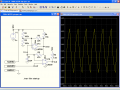
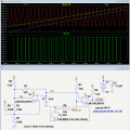
Here's the circuit modified to give a 0-100% duty-cycle for a 0V to 2.5V input.

Edit: If you want 100% to 0% duty-cycle with 0-2.5V input, just reverse the input connections to U2

upload_2017-10-24_15-5-56.png
 
Last edited:

crutschow

Joined Mar 14, 2008
38,578
would you look at the data sheet linked here and tell me what that Hall sensor would have as it's output?
I'm confused.
I thought you already had a Hall sensor. :confused:

That Honeywell sensor has an output from about 1V to 1V below the supply voltage maximum as shown below from the data sheet:

upload_2017-10-24_16-19-21.png
 

Thread Starter

dlatch

Joined May 15, 2016
91
I was searching about for something with more than a 2.5 volt swing. I guess I'll purchase a few of that one.

Meanwhile....I did the mods from your diagram. It is better but it still does not go much below 30%.The full is better...it wasn't totally clean at 100% before. But the bottom is still an issue

what values can I adjust to lower the saw wave a bit further?

OR

would it be more adjustable with a different oscillator? Is the typical 3 comparator Tri wave easier to adjust? like the .jpg below?
 

Attachments

crutschow

Joined Mar 14, 2008
38,578
I did the mods from your diagram. It is better but it still does not go much below 30%.
Are you sure you made all the resistor changes I posted?
It shouldn't be that far off.
what values can I adjust to lower the saw wave a bit further?
You can try reducing the value of R4.
Is the typical 3 comparator Tri wave easier to adjust? like the .jpg below?
It may be.
The lower-left 100k resistor can be varied to control the center (average) voltage of the triangle-wave.
The 47k can be varied to control the triangle-wave amplitude.
 

Thread Starter

dlatch

Joined May 15, 2016
91
Perhaps the values I added were not close enough. I will do some adjusting. Thank you as always.

I have also been reading about magnet placements and movements. My current "head on" set up is NOT optimum. The chip I'm using may be just fine.
 
Top