Facebook
 Google
 GitHub
 Linkedin
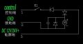
I am making a diy Vending machine . so i bought this motor to vend the snacks. But i have problem controlling this motor. It has 3 pins . I want to control this motor using arduino
Attachments
-
 2.1 MB Views: 64
 -
 2.2 MB Views: 66