How to control the field current of an alternator by using PWM?

MaxHeadRoom

Joined Jul 18, 2013
28,619
I have built one with a simple LM311 and a Mosfet, but this results in a simple variable pulse, not PWM but the principle is very similar.
This assumes no regulator is currently present in the alternator.
A simple PWM could be used but would involve a little more deign.
Max.
 

tcmtech

Joined Nov 4, 2013
2,867
That, and given how a common alternator is designed they basically already use PWM via their feedback loop to control their voltage anyways. The rotor field coils are pretty much switched full on full off as the feedback circuit senses whether or not the output voltage is correct or not. Its just a matter of how long and how often it need to do it to maintain the output voltage where it needs to be given the combination of the load and mechanical speed of the rotor.
Variable frequency switching rate on top of basic PWM control. A process you wont throw together on your own with DIY circuitry for the $10 - $15 an off the shelf universal or refitted regulator from another make of alternator would cost you.
 

MaxHeadRoom

Joined Jul 18, 2013
28,619
From the posting in another forum the OP does not need voltage regulation but variable voltage into a fixed load for an exercise bike.
IOW, vary the voltage and the current accordingly.
Max.
 

ian field

Joined Oct 27, 2012
6,536
Hello,

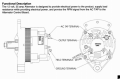
How can I use a PWM to control the field current of an alternator? That is, a regulator to vary the strength of the magnetic field?
The original electromechanical regulator boxes for car dynamos more or less did.

The main difference is the alternator spins the field coil, the brushes don't need to carry so much current and slip rings instead of segments for almost no electrical noise - later designs had the field coil stationary as well, coaxial pole pieces coupled the flux to the rotor.

Pretty sure I've seen published projects for PWM alternator control and there's various online magazine archives - if you've got some time on your hands.........

If none of those work as you hoped, you can always try a LPF between the PWM and field coil.
 

MaxHeadRoom

Joined Jul 18, 2013
28,619
The original regulator that replaced the electro-mechanical version was an electronic variable frequency version of it, this caused radio interference, so the present types are PWM.
From what I have read in other posts, the OP needs variable voltage control, not regulation of a fixed voltage.
Max.
 

ian field

Joined Oct 27, 2012
6,536
The original regulator that replaced the electro-mechanical version was an electronic variable frequency version of it, this caused radio interference, so the present types are PWM.
From what I have read in other posts, the OP needs variable voltage control, not regulation of a fixed voltage.
Max.
There were plenty of linear automotive regulators in the early days - one of the dominant motivations is that PWM is cheaper than big heatsinks.

I've never seen any documentation relating to a variable frequency type.
 

MaxHeadRoom

Joined Jul 18, 2013
28,619
There were plenty of linear automotive regulators in the early days - one of the dominant motivations is that PWM is cheaper than big heatsinks.

I've never seen any documentation relating to a variable frequency type.
I have built and marketed one for 240v scrap yard cranes, it simulated the original which simply switch to +ve or Common depending on the level of the DC, works very accurately,
This was the principle of the older mechanical one the frequency of the contact closure depended purely on voltage out.
Max.
 

tcmtech

Joined Nov 4, 2013
2,867
I don't really see the point of making a PWM control for a alternator thats just being used as an adjustable physical load on a exercise bike.

There's nothing to be gained from it since all it's doing is working as an overly complicated mechanical brake for the bike anyway.
 

ian field

Joined Oct 27, 2012
6,536
I have built and marketed one for 240v scrap yard cranes, it simulated the original which simply switch to +ve or Common depending on the level of the DC, works very accurately,
This was the principle of the older mechanical one the frequency of the contact closure depended purely on voltage out.
Max.
The contact vibrated and a higher output voltage caused it to spend more time vibrating away from the field coil fixed contact - it was essentially PWM.

The frequency probably did vary - but it was an incidental action that was of too little consequence to bother doing anything about it.
 

tcmtech

Joined Nov 4, 2013
2,867
The way I saw the mechanical voltage regulators operation was that they were fairly even in frequency at light loads due to the inherent mechanical movement aspect of their design and the rather fixed rate their coil and magnetic properties worked at.

At heavier loads they traded off frequency of operation for longer duty cycle which in my books is definable as a variable frequency PWM control..

As for the broad band RF they gave off that's what most any spark discharge does if not damped properly which in the case of the old mechanical voltage regulators a wire wound resistor across the points circuit located underneath the main regulator body was about all they had. It cut done on points wear due to arcing but I think they work pretty well ad little broad band radio transmitter antenna in return.

Still a ignition condenser across each the 'F', 'A' and 'BAT' terminals on the regulators and one on the 'A' terminal of the generator to shnut the RF noise to ground made a world of difference in what noise they would give off. Its how I first learned about RF and how to clean it up on old farm trucks and tractors back when I was a kid and any machine with a functioning AM radio was better than nothing if you could just get the machines electrical noise knocked out well enough to hear what Paul Harvey had to say. ;)
 

ian field

Joined Oct 27, 2012
6,536
The way I saw the mechanical voltage regulators operation was that they were fairly even in frequency at light loads due to the inherent mechanical movement aspect of their design and the rather fixed rate their coil and magnetic properties worked at.

At heavier loads they traded off frequency of operation for longer duty cycle which in my books is definable as a variable frequency PWM control..

. ;)
There's certainly a variable frequency element - a car engine doesn't have constant RPM.

AFAICR: The moving contact in the old regulator boxes had a mechanical resonance - it at least tried to stay on one fixed frequency.

Since the moving contact is constantly vibrating; there's no "critical mass" effect to shift it from one position to the other - it tends to reach equilibrium nearer or further from the fixed contact depending on the average flux in the solenoid coil. The NO & NC contacts act as limit stops, if the average solenoid current tends more one way than the other - the moving contact will spend more time in contact with that fixed contact than the other.

Its PWM by any definition I've ever read about.
 

MaxHeadRoom

Joined Jul 18, 2013
28,619
I take the current generally accepted definition of PWM is where the Pulse Freq is fixed and the width is varied.
The old style of mechanical and the immediate electronic version that replaced it did not operate at a fixed frequency.
Max.
 

ian field

Joined Oct 27, 2012
6,536
I take the current generally accepted definition of PWM is where the Pulse Freq is fixed and the width is varied.
The old style of mechanical and the immediate electronic version that replaced it did not operate at a fixed frequency.
Max.
There's a grey area - fixed on time PWM increases the off time by reducing frequency.

Some Fidelity colour TVs used that type of regulation.
 
Top