How to build op-amp amplifier for thermocouple

Thread Starter

Don_Fila

Joined Nov 26, 2021
172
OK, but most of the soldering type equipment that I have seen uses 24 volts for the heater.
Those readings may indicate a thermocouple, I am not sure. And if the case got that hot then the mains voltage is not what the heater is intended to opwerate on, it seems. Do you have the rest of the system so that you could measure the voltage that the heating core is supposed to use? It does not seem like it would be 220 volts.
OK, but most of the soldering type equipment that I have seen uses 24 volts for the heater.
Those readings may indicate a thermocouple, I am not sure. And if the case got that hot then the mains voltage is not what the heater is intended to opwerate on, it seems. Do you have the rest of the system so that you could measure the voltage that the heating core is supposed to use? It does not seem like it would be 220 volts.
I don't really understand exactly what you mean. Can you switch heating core from 24vac or do you mean inverting the voltage?
 

Attachments

MisterBill2

Joined Jan 23, 2018
27,980
What I mean is that the solderig staions that I am familiar with and have worked on all had an internal transformer so that the voltage sent to the heating element was 24 volts AC, isolated from the mains. But the maximum wattage of those units was 50 watts, I think. Quite different from the 2000 watt air heater system. But certainly making the case glow red is far too hot. Are you intending to use the heater for a different purpose? Why not use the original control system designed for it? That would avoid all of the challenges you are facing.
 
OP, that is your typical hot air heating element with thermocouple, used in low cost chinese stations. I doubt it's 2,200W and another safety issue is the nozzle must be PE grounded but it's stainless steel- so soldering the tube is not easily possible.

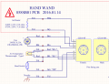
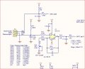
Example 858D+ hot air station schematic snippet. They use a single op-amp stage with OP-07C to amplify the type J thermocouple which typically makes 27.4mV at 500°C/932°F so a voltage gain of 100 would give 2.74V which is something you can work with. AC hum pickup is a problem, you need filtering as well.
The next part of the circuit would be a comparator and latch so it shuts off power to the heating element if things got too hot.
You can also buy entire control boards for low cost. The whole project has safety aspects because the wand either will electrocute you or burn down your house if your circuit does not work and heat is stuck on. These wands are very dangerous, from the wiring on the tiny PCB not having decent spacings, to the GX connector being hazardous live - all the time on cheap stations where the power switch switches Neutral, not Hot, to lack of a thermal cutoff fuse.

YouYue 858D_plus wand schematic REVISED.PNG858D thermocouple amp.JPG

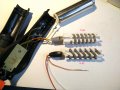
858D+_heater_ohms.jpg
 

MisterBill2

Joined Jan 23, 2018
27,980
OP, that is your typical hot air heating element with thermocouple, used in low cost chinese stations. I doubt it's 2,200W and another safety issue is the nozzle must be PE grounded but it's stainless steel- so soldering the tube is not easily possible.

Example 858D+ hot air station schematic snippet. They use a single op-amp stage with OP-07C to amplify the type J thermocouple which typically makes 27.4mV at 500°C/932°F so a voltage gain of 100 would give 2.74V which is something you can work with. AC hum pickup is a problem, you need filtering as well.
The next part of the circuit would be a comparator and latch so it shuts off power to the heating element if things got too hot.
You can also buy entire control boards for low cost. The whole project has safety aspects because the wand either will electrocute you or burn down your house if your circuit does not work and heat is stuck on. These wands are very dangerous, from the wiring on the tiny PCB not having decent spacings, to the GX connector being hazardous live - all the time on cheap stations where the power switch switches Neutral, not Hot, to lack of a thermal cutoff fuse.

View attachment 254514View attachment 254515

View attachment 254516
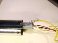
The head in this photo HAS a good grounding connection to a lug crimped onto a wire and screwed to the shell. The ground wire is yellow with a green strip, easily visible. And that stainless is easy for me to solder to.
 
This is what I found, just a ground wire twisted around a spot-welded tang. I tried to fix but could not solder to it at all. Silver solder sorta worked. It might be chrome plated steel the sleeve is made out of, but usually one can solder that after filing it rough.

2.2kW with 20AWG wire, ha some aspects of OP's heater are a disaster.858 PE ground.jpg
 

Thread Starter

Don_Fila

Joined Nov 26, 2021
172
Hello friends
I have understood everything you have said, but I got something to tell you now and I only need help from you all. Three months ago I build a smd rework station which I have been using till now and everything works fine which I don't encounter any problem. But my fear is about the heating core which I don't want it to get overheated and burn the handle and myself as well. Well, for that reason I always set it to medium temperature to work with it. As a professionals here in this discussion forum I need your advice and help on how to build overheating protection for my homemade rework station to shut down over heating automatically when it's overheating and start when it cools. Your help will highly be appreciated.

Note:
Some members will ask me why don't
I get new smd rework station instead
By building your own. I just want to
tell you that here in my country
the inexpensive smd rework station
are not of good quality and it doesn't
last long, I once purchase one of the
inexpensive smd rework station and
it doesn't last for even two months
comparing to mine, which it almost
Getting to four months and I'm using it till now. And also
just wanna tell you my friends
that I can't afford for the expenditure
SMD rework station. Please help me
to build overheating protection
For my smd rework station.
 

MisterBill2

Joined Jan 23, 2018
27,980
If the present temperature control works, then one reasonable option will be adding an external thermal switch on the outside of the device. That can provide a positive shutoff in the event of an excessive temperature rise, and not risk causing any change in the present temperature control system.
You could also use a thermister , which would be much smaller and simpler to attach. Detecting an overheat could then be done with a simple camparator circuit, since the voltage change with a thermistor is much greater.
 

Thread Starter

Don_Fila

Joined Nov 26, 2021
172
If the present temperature control works, then one reasonable option will be adding an external thermal switch on the outside of the device. That can provide a positive shutoff in the event of an excessive temperature rise, and not risk causing any change in the present temperature control system.
You could also use a thermister, which would be much smaller and simpler to attach. Detecting an overheat could then be done with a simple comparator circuit, since the voltage change with a thermistor is much greater.
Thanks! Very much I really like how you answered questions
 

Thread Starter

Don_Fila

Joined Nov 26, 2021
172
If the present temperature control works, then one reasonable option will be adding an external thermal switch on the outside of the device. That can provide a positive shutoff in the event of an excessive temperature rise, and not risk causing any change in the present temperature control system.
You could also use a thermister, which would be much smaller and simpler to attach. Detecting an overheat could then be done with a simple camparator circuit, since the voltage change with a thermistor is much greater.
Yeah the controls work fine
 

MisterBill2

Joined Jan 23, 2018
27,980
It's informative.

Please do you have any circuit diagram?
I have seen comparator circuits on threads but I don't recall which ones. BUT there are some folks here in the crowd who should be able to recall a thread with a comparator that would provide that function. And there are lots of comparator circuits published on various websites. But you will need to know what temperature you want to switch the heater off at. And you will need to locate a thermistor that will work at that temperature.
 

Thread Starter

Don_Fila

Joined Nov 26, 2021
172
The
I have seen comparator circuits on the threads, but I don't recall which ones. BUT there are some folks here in the crowd who should be able to recall a thread with a comparator that would provide that function. And there are lots of comparator circuits published on various websites. But you will need to know what temperature you want to switch the heater off at. And you will need to locate a thermistor that will work at that temperature.
The temperature ranges from 200c,250c,300c,350c,400c,450c and 480. I will like to switch off the heater when the temperature is greater than 480c.
 

MisterBill2

Joined Jan 23, 2018
27,980
OK, so you probably need a thermistor that is good up to 500C just to stay in it's safe temperature range. Not sure how the outside temperature varies with the inside temperature, and so a bit of experimenting would be needed. AND you will need some adhesive that is good for that temperature range as well. I was thinking that you would glue the thermistor to the outside of the steel shell.
 

Thread Starter

Don_Fila

Joined Nov 26, 2021
172
OK, so you probably need a thermistor that is good up to 500C just to stay in its safe temperature range. Not sure how the outside temperature varies with the inside temperature, and so a bit of experimenting would be needed. AND you will need some adhesive that is good for that temperature range as well. I was thinking that you would glue the thermistor to the outside of the steel shell.
I think when it's overheating the outside and inside temperature will be the same
 

Thread Starter

Don_Fila

Joined Nov 26, 2021
172
OK, so you probably need a thermistor that is good up to 500C just to stay in its safe temperature range. Not sure how the outside temperature varies with the inside temperature, and so a bit of experimenting would be needed. AND you will need some adhesive that is good for that temperature range as well. I was thinking that you would glue the thermistor to the outside of the steel shell.
I think when it's overheating the outside and inside temperature will be the same. And for the glue do you mean heat resistance glue?
 

MisterBill2

Joined Jan 23, 2018
27,980
I think when it's overheating the outside and inside temperature will be the same. And for the glue do you mean heat resistance glue?
YES! That will need to hold the sensor in place, even at the high temperature, and provide some mechanical protection during normal use. So the requirement is rather demanding. It might work also to have the thermistor inside the handle assembly, mounted to the heater shell inside, near to the end. It looks like there may be enough room inside, maybe.
 

Thread Starter

Don_Fila

Joined Nov 26, 2021
172
I think when it's overheating the outside and inside temperature will be the same. And for the glue do you mean heat resistance glue?
If you
YES! That will need to hold the sensor in place, even at the high temperature, and provide some mechanical protection during normal use. So the requirement is rather demanding. It might work also to have the thermistor inside the handle assembly, mounted to the heater shell inside, near to the end. It looks like there may be enough room inside, maybe.
Yes there is enough room inside the handle which the sensor cam be added
 

MisterBill2

Joined Jan 23, 2018
27,980
One more thought, another option, would be to use one of the thermal fuses like the ones used in cheap equipment, connected in series with the heater element. That would prevent extreme overheating if the control system failed. It would need to be replaced at that point, but it would prevent an excessive overheating.
The question then is how often do you anticipate that it would overheat?? What would cause an overheated condition??
 

Thread Starter

Don_Fila

Joined Nov 26, 2021
172
One more thought, another option, would be to use one of the thermal fuses like the ones used in cheap equipment, connected in series with the heater element. That would prevent extreme overheating if the control system failed. It would need to be replaced at that point, but it would prevent an excessive overheating.
The question then is how often do you anticipate that it would overheat?? What would cause an overheated condition??
It's very easy to anticipate because the cheap equipment, connected in series with the heater is used to sense the temperature to show if it's at set range or it's overheating and if it at the set rang, then use it with whatever you want to work with but if it's not in the set rang, shut down it to cool.

What would cause an overheating condition?

An overheating condition is caused by overheating this is when the temperature that suppose to work on the set range passes to undefined set range. For example:

Fixed Set Ranges:
200c
250c
300c
350c
400c
450c
480v

Undefined Set Rang:
500
550
600
650
 
Top