Facebook
 Google
 GitHub
 Linkedin
Hi everyone,
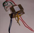
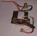
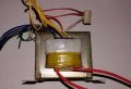
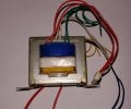
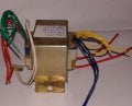
I have got a old transformer for building a variable dc power supply, the transformer is in good condition and has 5 different taps for 5 different voltage outputs.
But the problem is that the transformer doesn't have a tag over it for the rated current, thus before using it in a circuit, First I would like to test the maximum current output of the transformer, I tried measusing it with multimeter and some resistance but it didn't worked for me as the multimeter is showing nothing.I have no idea how to measure the maximum current output of a unknown transformer, pls help me !