How does the transistor work in the circuit

Thread Starter

zemanekj

Joined Jan 31, 2019
58
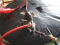
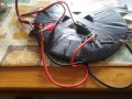
Help me out folks, I'm having a hard time understanding how transistors work, especially in this circuit
(which you can see in this video -
- from 0:56 - 1:32)
It's driving me crazy. I want to build this circuit but should obviously understand how it works first. I'm reading online about how joule thief works, and how transistors work but still need some help wrapping my head around it.

Thank you.
 

crutschow

Joined Mar 14, 2008
34,459
Basically a BJT (bipolar junction transistor) amplifies the current going into the base-emitter my a current-gain factor called either β (beta) or Hfe. The value for the current current is for a small BJT is typically in the 100-300 range.
Thus a 1mA current into the base-emitter will cause 100-300mA to flow from collector to emitter (assuming the collector is biased with a positive voltage from collector-emitter for a NPN type BJT).

So what do you want to know about that with respect to the circuit you want to build?
In that circuit there's a coil with two concentric wound wires that provide magnetic coupling between the two wires.
This generates a signal from the collector current winding to the base winding that generates an oscillation of the current in the two coils.
This provides a high frequency AC current that magnetically couples into an adjacent coil, as a transformer, generating a voltage in the adjacent coil the lights the LED.
 

wayneh

Joined Sep 9, 2010
17,498
The part that’s not obvious is why it oscillates. It has to, for that circuit to work. The role of the transistor is to act as an on/off switch for current in the coil.

I always lose my mind trying to understand oscillation instead of steady state.
 

Thread Starter

zemanekj

Joined Jan 31, 2019
58
I am working on putting together what is in this video:

But I can't get mine to work. I'm using these for the circuit:
The wire - https://www.amazon.com/gp/product/B078YYLT5T/ref=ppx_yo_dt_b_asin_title_o01_s00?ie=UTF8&psc=1
The transistor - https://www.amazon.com/gp/product/B018DMVGJU/ref=ppx_yo_dt_b_asin_title_o02_s00?ie=UTF8&psc=1
The resistor - https://www.amazon.com/gp/product/B011NAAYWO/ref=ppx_yo_dt_b_asin_title_o03_s00?ie=UTF8&psc=1

I have the pancake coil wrapped and tapped together to make sure it stays the way it should. I think I have all of the wiring correct so I'm not sure why it's not working. I'm using a DC power supply but it wont go above 1.4 volts.

Also, to see if it is working I have a simple coil of magnet wire attached to a voltmeter which I am holding just above the primary coil.

I know it looks like a dangerous messy, trust me I plan on making this a more clean organized circuit once I get it to work. See all of the pictures to help get an idea of what I am talking about.

Do you gentlemen see something I don't?
 

Attachments

AlbertHall

Joined Jun 4, 2014
12,347
I'm using a DC power supply but it wont go above 1.4 volts.
That suggests your power supply can't supply enough current or your circuit is drawing more current than it should.
Or, another thought, if you are slowly ramping up the voltage that may prevent it from oscillating. Try setting the voltage and then connect to your circuit.
 
Top