Facebook
 Google
 GitHub
 Linkedin
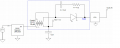
Following an existing circuit I have been analyzing.

Here, there is no confusion with the working of buck regulator output 3.3 V. But with the blue-rectangle section, input to the LDO (Vout2) is taken. When it measures, Vout3 = 5 V. So obviously Vout2 would be greater than 5 V. I am trying to figure out how this circuit will work and how to calculate the voltage Vout2 theoretically. Coupled inductor (N1=N2) inductance is 10µH.
Can anyone suggest how to calculate the input voltage (Vout2) to the LDO and the working of this section.
Thanks for the support.
MOD:tidied your images.E
Last edited by a moderator:
")