What are the resistances between the 3 wires? That will give an idea of the winding construct.
Likely to be split phase motor and one winding will be fed through a capacitor.
Speed control is most likely using external resistors or capacitors.
Yes, most likely you have a PSC, Permanent Start Cap motor, the pair of joined windings are most likely equal in resistance, if so either winding can be used for start/run, making it a bi-directional motor.
Yes, most likely you have a PSC, Permanent Start Cap motor, the pair of joined windings are most likely equal in resistance, if so either winding can be used for start/run, making it a bi-directional motor.
As has been suggested, you need to measure the resistance between each conductor, in order to get an idea what connection is required, you also need the capacitor that it should have had originally.
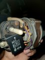
It appears the cap is there in the pic, the black cube.
As has been suggested, you need to measure the resistance between each conductor, in order to get an idea what connection is required, you also need the capacitor that it should have had originally.
It appears the cap is there in the pic, the black cube.
No worries man, I will wait for you.
Thank you so much for trying to help me out in here.
————————————————————
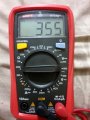
So nothing appeared in 200 range, So I switched to 2000.
Here are the values
Red + Grey = 355
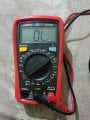
Red + Blue = None
Blue + Grey = None
Blue + Red = None
Resistance only appears between Red and Grey as 355, None appears between Blue wire and Red, Grey wires.
I checked the resistance without my hands touching the leads.
When you say none do you really mean no resistance (Zero ohms.) or do you mean infinite resistance (Meter displays 0L).
Can you also measure the resitsnce between the capacitor connections and between the capacitor terminals and the red, grey anf blue wires.
When you say none do you really mean no resistance (Zero ohms.) or do you mean infinite resistance (Meter displays 0L).
Can you also measure the resitsnce between the capacitor connections and between the capacitor terminals and the red, grey anf blue wires.
With the test leads NOT connected to anything or each other the meter will read 0L This means that the meter can't read the value of such a high resistance. With the meter set to the 2000 ohm (As in post #14) it can't measure a resistance of greater than 2000 ohms so it will display 0L. With the test leads shorted together it should read 0 but in practice it will probably read some low value of resistance (Say 0.5 ohms.) This due to the fact that the test leads have some resistance.
We would not expect any motor winding on this type of motor to have a resistance of more than 2000 ohms so it looks like the blue wire is not connected to the winding directly. It could be connected to the winding via the capacitor but the capacitor would read as an infinite resistance.
If it is a PSC motor as Max suspects it would have two windings. One end of each windig would be joined together. this would be connected to one of the supply leads. the capacitor would be connected between the other ends of the windings. If the other supply lead is connnected to one end of the capacitor the motor will rotate in one direction. if it is connected to the other end of the capacitor it would rotate in the other direction.
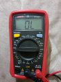
Okay, I tried switching from 2000 to 20K to see if I get any readings, Still it showed as 0L.
There's only 3 wires coming out of the motor, A capacitor is already connected to two wires coming out from the motor by the manufacturer already. I have attached a picture of the capacitor and you can see White and Purple wires are the one connected to it.
So I have only 3 wires coming out from the motor for power connection which are RED, BLUE, GREY. I have commented the resistance values between each other above.
My goal is to connect this motor to a stand fan. But usually as I have seen fan motors comes with 4 wires (if there was an earth wire it will be 5 wires.) So out of those 4 wires one will be ground and other 3 are used for different fan speeds.
But again in here this motor comes with only 3 wires.
I don't know which wire to connect and where to connect.
It would be great if you can tell me exactly how to connect each of these wires to power?
This is why I would like to know the resistance three wires abnd the capacitor terminals. I have a theory that the blue wire connects to the jubction of the two windings via a thermal fues which has gone open circuit.
I am trying to get evidence to see if that theory may be correct.
 Facebook
 Google
 GitHub
 Linkedin