How can this be??!!

Thread Starter

MaxHeadRoom

Joined Jul 18, 2013
30,660
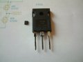
I recently got hold of some miniscule DUAL MOSFETs; they are incredibly small for the ratings!

BUK7KBR7 & Si7232. Both 8 pin devices!
How can they possibly equal two of the full size counterpart
 

Attachments

panic mode

Joined Oct 10, 2011
4,982
i agree that it is remarkable how small things are gettings and who knows what we are going to see in the next few years.
but... they are not exactly equal...

larger counterparts can handle way higher voltage. also they can be mounted on a heatsink and handle more power. Si7232 taps out at less than 15W while IRFP460 is ok with up to 280W.

the die size may not be that different but robust large THT package has massive leads requiring giant package so that it does not split when handled. this goes away with smd and very short leads.

btw. many loads in automotive applications tend to be brief - move seat, adjust mirror, etc. so couple of seconds, not continuous use. also materials could be different. anything using SiC or GaAs is likely to be considerably smaller.
 
Last edited:

Ian0

Joined Aug 7, 2020
13,132
They both switch 20-odd Amps. IRFP460 is rated at 500V, BUK7K25 at 40V, and the Rds(on) figures reflect that. 10 times higher for the device with 10 times the voltage rating. So the 500V device will always need to dissipated more heat.
Also, the IRFP460 was designed at a time when people actually used MOSFETs in linear mode!
 

Ian0

Joined Aug 7, 2020
13,132
I will give it a try, hopefully my air gun has the required Heat!
If you're using a paint-stripping gun, turn the air speed down, otherwise you will be picking them up off the floor!
And don't work on a formica tabletop, otherwise when you get to the edge of the board, you'll singe the formica and it really stinks.
I work on an upturned baking tray - the metal spreads the heat and preheats other parts of the board. But we have stencils, solder paste and a proper temperature controlled infra-red reflow oven at work.
 

MisterBill2

Joined Jan 23, 2018
27,519
First, read the complete data sheet, there may be some "interesting limitations" attached to that current rating. Also, read very carefully about the mounting and heat sinking requirements.
My point being that, as always, there are trade-offs. Some of them take some research to discover.
 

Thread Starter

MaxHeadRoom

Joined Jul 18, 2013
30,660
First, read the complete data sheet, there may be some "interesting limitations" attached to that current rating. Also, read very carefully about the mounting and heat sinking requirements.
My point being that, as always, there are trade-offs. Some of them take some research to discover.
Been on holiday , not seen for a week or so?? :p

I have the data sheet for a few, I think I will go with the one-Mosfet type body instead of the dual, even so they are same physical size,
A few example complete circuit designs are out there, Pololu stepper for one. Around the DRV8711.

(Board reverse side)
1758377178875.png
 

MrAl

Joined Jun 17, 2014
13,704
I will give it a try, hopefully my air gun has the required Heat!
Hi,

Don't underestimate the power of solder paste. It's wonderful stuff. You can spread it all over the place and if it's not too-too thick it will wet the pads and the pins through capillary action. The spaces between pins become open just like you would want. It's amazing really.
You would think that by spreading the solder paste in a continuous line across four pins would cause all four to short out when you hit it with the heat gun, but that's not what happens. It turns a bright chrome color and seeks out the pins and the pads, provided they are clean of course.
Once you try it, if you never did before, you'll be hooked for life :)
 

Thread Starter

MaxHeadRoom

Joined Jul 18, 2013
30,660
Don't underestimate the power of solder paste. It's wonderful stuff.
Once you try it, if you never did before, you'll be hooked for life :)
I usually use the common yellow soldering resin, work the same way??
I have seen that method on youtube ,BTW.
 

Ian0

Joined Aug 7, 2020
13,132
Hi,

Don't underestimate the power of solder paste. It's wonderful stuff. You can spread it all over the place and if it's not too-too thick it will wet the pads and the pins through capillary action. The spaces between pins become open just like you would want. It's amazing really.
You would think that by spreading the solder paste in a continuous line across four pins would cause all four to short out when you hit it with the heat gun, but that's not what happens. It turns a bright chrome color and seeks out the pins and the pads, provided they are clean of course.
Once you try it, if you never did before, you'll be hooked for life :)
Surface tension is a marvellous thing! It seems to work perfectly for 1.27mm pin-spacing. reasonably well at 0.65mm and becomes hopeless at 0.5mm
 

MrAl

Joined Jun 17, 2014
13,704
Surface tension is a marvellous thing! It seems to work perfectly for 1.27mm pin-spacing. reasonably well at 0.65mm and becomes hopeless at 0.5mm
Oh really? I don't think I've ever done a package with that pin spacing.

How do they solder them then? There must be a way and I have an idea what is involved.
There would be various constraints like viscosity, thermal mass, temperature gradient, etc., etc. The one that has the largest effect is probably the volume of paste. Too much volume and solder bridges occur regularly, and secondly, too little flux means surface tension would be too high so poor wetting.
 
Last edited:

Futurist

Joined Apr 8, 2025
748
I can't imagine trying to solder these tiny devices. When I was a teenager and learning the subject at college and making stuff (late 70s) it was easy.

All chips were DIL devices (TTL/CMOS + larger chips sometimes) and discrete transistors were the norm.

We did almost all circuits using SRBP boards:

1758383252310.png

That was the hobby for me back then, I miss those days.
 

Ian0

Joined Aug 7, 2020
13,132
Oh really? I don't think I've ever done a package with that pin spacing.

How do they solder them then? There must be a way and I have an idea what is involved.
There would be various constraints like viscosity, thermal mass, temperature gradient, etc., etc. The one that has the largest effect is probably the volume of paste. Too much volume and solder bridges occur regularly, and secondly, too little flux means surface tension would be too high so poor wetting.
1. Do the best you can with the solder paste. If you haven't got too much on, most pins will have soldered properly
2. For those that haven't and are bridged to their neighbours, apply a little rework flux, then using a 3mm chisel tip, drag the solder down the pins. Usually that sorts it out.
3. If it's worse than that, drag the solder to the end of the line (helps if the board is tilted so that it is downhill) then remove it with a solder sucker.
Although it seems counter-intuitive, QFNs tend to be less of a hassle than QFPs.
 

Futurist

Joined Apr 8, 2025
748
There might be an adapter one can get, a bit like this:

1758388466627.png

That's not the same kind of SMD though, the MOSFET appears to packaged as a PowerPAK® 1212-8, but there might be something similar one can get. That makes the device easy to reuse and experiment with.
 
Last edited:
Top