How can i use LM3914 to display state of charge ? -schematic attached.

Thread Starter

anishkgt

Joined Mar 21, 2017
549
Hello All,

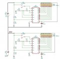
Can somebody help to determine how to measure the voltage of 3 Cells here ? I know how its done with one cell but 3 is kinda of confusing to me. The circuit was suggested by Dave in his video

Is it ok to use the same value for this schematic or should these be changed depending on the total voltage, like here it is 12.3v
LM3914.jpg
 

Attachments

ericgibbs

Joined Jan 29, 2010
18,739
hi anish,
Are you asking how to measure the individual battery voltages of the 3 batteries connected in series, either with 1. Lm3914 or 3, LM3914's.?
It is not clear which.
E
 

Ya’akov

Joined Jan 27, 2019
9,044
What is the chemistry of the cells? Unless it is some lead acid variety, cell voltage is not a reliable way to tell state of charge.

In litihium varieties, state of charge is most reliably determined with a Coulomb counter. There are ICs that implement them readily available.

Maybe you don’t mean state of charge and simply need to read out the battery voltages, for say, balancing?
 

Thread Starter

anishkgt

Joined Mar 21, 2017
549
What is the chemistry of the cells? Unless it is some lead acid variety, cell voltage is not a reliable way to tell state of charge.

In litihium varieties, state of charge is most reliably determined with a Coulomb counter. There are ICs that implement them readily available.

Maybe you don’t mean state of charge and simply need to read out the battery voltages, for say, balancing?
Chemistry is Li-ion. Just need to know the voltages rather than the state of charge. Yes for balancing. Basically a visual indicator like a meter. Don't need to be precise. A fairly simple visual voltage indicator.
 

Ya’akov

Joined Jan 27, 2019
9,044
Chemistry is Li-ion. Just need to know the voltages rather than the state of charge. Yes for balancing. Basically a visual indicator like a meter. Don't need to be precise. A fairly simple visual voltage indicator.
In that case, the LM3914 is the classic way to do it for a single cell or battery but I am not sure it will behave as expected in your application.
 

Thread Starter

anishkgt

Joined Mar 21, 2017
549
Hi anish
I have shown a two battery circuit, it is not really viable.
The battery sense resistor dividers are all in series.
E
Based on your suggestion would this be correct ?

In your suggestion is it correct to have R1 and R2, R3 and R4, R9 and R10 share the common ground. ? Pin 6 determines the HIGH voltage so shouldn't the other side of R1 be connected to BAT_1 rather than GND?
LM3914.jpg
 

Thread Starter

anishkgt

Joined Mar 21, 2017
549
In that case, the LM3914 is the classic way to do it for a single cell or battery but I am not sure it will behave as expected in your application.
To measure the voltage of each cell with a DM this is how its done. So we are just replacing the DM probes with the LM3914.
 

ericgibbs

Joined Jan 29, 2010
18,739
hi anish,
You cannot connect all 3, LM3914 common/ground together.

On the diagram I posted the common line of the upper LM3914 would be connected to +Vsupply of the lower LM3914
the problem with that is the 10K dividers on pin #5, for all 3, LM3914 would all be in series, from the top battery, via the middle battery and then the lower battery.

Pin5's of the LM3914, would not read the correct voltage for its own battery.
E
 

ericgibbs

Joined Jan 29, 2010
18,739
hi,
OK, so R1 and R2 will need recalculating to suit the 4.9V battery.
The other LM3914 resistor values will be the same as the new R1, R2 values.

Can you calc that ok.?
E
 

Thread Starter

anishkgt

Joined Mar 21, 2017
549
hi,
OK, so R1 and R2 will need recalculating to suit the 4.9V battery.
The other LM3914 resistor values will be the same as the new R1, R2 values.

Can you calc that ok.?
E
But how are they connected, i mean to measure each cell in a 3s configuration for example. Since you said R1 and R2 would be in series with the other two pairs.

R2 as he had mentioned is used for the brightness of the LED and R1 is the LOW voltage window.
 

ericgibbs

Joined Jan 29, 2010
18,739
OK.
It is possible to get a fairly accurate reading for each battery.
The point I was concerned about is the Load current is flowing in the 6 off 10k resistors, which may effect the accuracy.
I would suggest you build the project.

Basically the top LM3914 considers the +Vsupply line of the next lower LM3914 as its common.
The 2nd LM3914 considers the +Vsupply line of the bottom LM3914 as its common.
The bottom LM3914 uses the actual 0Vas common.

Draw a sketch on how you see it connected and will check it out.
E
 

Thread Starter

anishkgt

Joined Mar 21, 2017
549
Basically the top LM3914 considers the +Vsupply line of the next lower LM3914 as its common.
The 2nd LM3914 considers the +Vsupply line of the bottom LM3914 as its common.
The bottom LM3914 uses the actual 0Vas common.
Isn't it how i had drawn ? sorry that was something i got confused and asked if it would really work. Maybe the 10k resistors can be reduced to 1k if the current would be a problem.
 
Top