hot mosfets in half bridge

Thread Starter

yoosefheidari

Joined Oct 26, 2013
10
hi
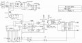
i use this schematic for a power supply and i have a problem
when i didn't connect transformer and mosfets have any load after 20 sec mosfets become very hot about 80 degree celsius!
i replace 15k res of SG3525 with 10k and 33ohm res with 100ohm(in bothes mosfets are hot)
what's the problem and what should i do?
 

Attachments

dl324

Joined Mar 30, 2015
18,326
Did you make substitutions for any component, e.g. the MOSFETs? Check the MOSFETs to make sure they're being turned on hard enough.

Regarding the case being 80C; what matters is the junction temperature.
 

wayneh

Joined Sep 9, 2010
18,104
Put a load in series with the MOSFETs until you get it sorted out, or reduce the supply voltage substantially. This should give you more time “on” without risking overheating, allowing time to measure gate-source voltages and such.
 

TechWise

Joined Aug 24, 2018
151
The MOSFET heating is caused by power being dissipated in it. This can happen in a few ways:
  1. The MOSFET is not being turned fully on or fully off. Under these conditions, the MOSFET behaves like a resistor with a large current passing through it with a large voltage across it. Large I times large V equals large Power ie. Heat. You can check this as @wayneh suggest by looking at Vgs.
  2. The MOSFET is being turned fully on or off but the load current is so high that the MOSFET heats up due to conduction losses. Even when the MOSFET is fully on, it still has a typical on-state resistance between source and drain. This will be shown in the datasheet as RDSon or similar. This will typically be in the order of milliohms however if the load current is in the hundreds of amps this still produces a significant power loss since P=I^2*R
  3. The MOSFET is fully on but it is being switched so fast that the switching loss is very high. Even with an effective gate drive circuit, when the MOSFET switches there is a brief period where it supports a high voltage across it with a high current flowing through it, this leads to a high power loss for a short space of time. This power loss is worse at high switching frequencies.
  4. The MOSFET is incorrectly connected and is now dead!
Option 1 is most likely but if the device has been overheated too much then it may be ruined.
 

ebp

Joined Feb 8, 2018
2,332
Since the circuit is being tested without the transformer connected, the ONLY possibility, other than connection that is simply wrong, is shoot-through current and this is only possible with inadequate gate turn-off drive or insufficient "dead time" when both FETs should be fully off. Inadequate turn-on is essentially irrelevant with no load. Of course poor layout can make a complete mess of operation.

Since the output voltage will be zero, the duty cycle will go to maximum. This is also irrelevant with no load, other than it means the dead time programmed by the timing components is critical since that will be the only dead time.

Looking at signals with an oscilloscope is necessary, but if this really is an AC-mains operated circuit it absolutely requires a good quality isolation transformer and even at that is potentially lethal.
 

Thread Starter

yoosefheidari

Joined Oct 26, 2013
10
thank you every one for answers
i change dead time by changing resistor from 500ns to 2us but result was the same
i saw signals in oscilloscope and everything was fine without any problem.
@TechWise
finally i realize that mosfets have another way to dissipate power and that is Oss capacitor.by this formula P =0.5cfv^2 we can calculate power dissipation and in my circuit it is P =0.5*0.000000000870*50000*310*310=2.09watt for each mosfet and for this mosfet(IRFP460) junction-to-ambient temp is 40c/w and 25c for room temp so mosfet temP become around 108 degree.
(IRFP460 Oss capacitor is 870pF)
 
Top