
 Facebook
 Google
 GitHub
 Linkedin

Hello everyone, im new here to be that i have asked that undefined situations,  respectively. But i can't follow an efficient way to understand these PIC families cause of low level coding Assembly?! (The cumulative homeworks are asked as regularly if they're replied well. ) However, i need to describe myself to get your reputable approachs as firstly;
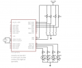
1.) Consider the following circuit, which has 4 input switches and 4 output LEDs. The input switches are used to read input from a 4-bit parallel binary information source that generates information in every second. The system should apply the following digital filter to this input data:
O[n]=(I[n] + I[n-1])/2,
here I[n] and I[n-1] represents current and last input data, the generated output is O[n] and it should be displayed using the LEDs.
a) Choose the XTAL frequency and the resistor values R1 and R2 proper to your design.
b) Design the firmware that implements the required digital filtering.Use interrupt in the design.
respectively. But i can't follow an efficient way to understand these PIC families cause of low level coding Assembly?! (The cumulative homeworks are asked as regularly if they're replied well. ) However, i need to describe myself to get your reputable approachs as firstly;1.) Consider the following circuit, which has 4 input switches and 4 output LEDs. The input switches are used to read input from a 4-bit parallel binary information source that generates information in every second. The system should apply the following digital filter to this input data:
O[n]=(I[n] + I[n-1])/2,
here I[n] and I[n-1] represents current and last input data, the generated output is O[n] and it should be displayed using the LEDs.
a) Choose the XTAL frequency and the resistor values R1 and R2 proper to your design.
b) Design the firmware that implements the required digital filtering.Use interrupt in the design.
Attachments
-
 82.8 KB Views: 25





