Facebook
 Google
 GitHub
 Linkedin
Hi everyone
Thank you so much for viewing this problem. I would be really grateful for any support you'd be able to give.
I am a beginner in building model planes and cars. I have the following models I am going to be building soon:
Basically, I want to fix battery-operated LEDs into these model planes which include static and strobe lights to enhance their realism and effect in the night.
The unfortunate bit is that I am not an experienced electrician to achieve this, I’m really sorry
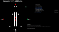
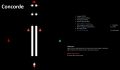
I’ve included three images that shows the layout of three different types of planes the flashing and static set of lights will fit to: generic, Concorde and the 787. These planes have a different flashing scheme. To make it easier for the expert electrician, I've attached some videos of hobbyists who have achieved the effect I'm trying to score.
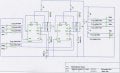
I definitely know I will need a battery of a particular voltage, a very small circuit board, super thin copper wires, double-sided tape to keep the wires in place inside the wings, some LEDs (the smallest maybe 1mm size head), soldering gun and lead, resistor (would I?), and a component which alters the flashing timings for a set of bulbs as per the images (no idea what this is called). The circuit board itself cannot be any more than 2.5cm wide due to the width of the fuselage. Basically, the gap inside the fuselage where the circuitboard will sit is around 2.5cm width and height. I came across this circuitboard a couple of weeks ago on the Conrad website and was wondering if this is the right thing I need?
https://www.conrad.de/de/tams-elekt...lc-15-einsatzfahrzeug-doppelblitz-218688.html
What I wanted to ask was if I could be given advice on what other components I would need to be able to achieve this effect and how I would go about to doing it please???
One thing I need to say is about the 787 flashing timings. These are the links to the best videos showing the 787s flashing scheme:
You can see that the way the lights flash on the 787, they’re not really flashes. They’re extremely unique and very different to normal strobe lights from other planes like the 747, A380 etc.
With regards to the Concorde, I was trying to achieve a flashing effect as seen in this video:
Also, for planes like the 747, A380, A350, I wanted to achieve an effect similar to this video:
So basically there will be:
I think in terms of the flashing, I need to be able to adjust how ‘quick’ the flash is by adjusting how long the power runs through the LED in one instance of a flash, and also I need to be able to adjust how long a gap there exists between each ‘flash’.
Thank you so much and I’m really sorry if I’ve not been able to provide any more specific information. If you need any other information, I’m more than happy to provide it.
Again I’m really thankful for any support you can provide to help me achieve this measure of perfection
- Yousuf.
Thank you so much for viewing this problem. I would be really grateful for any support you'd be able to give.
I am a beginner in building model planes and cars. I have the following models I am going to be building soon:
- 1/114 Revell 747 Shuttle Carrier Aircraft w/ Space Shuttle
- 1/114 Revell Boeing 787-8
- 1/114 Revell Boeing 747-8i
- 1/114 Revell Boeing 777-300ER
- 1/72 Revell BAC Concorde
Basically, I want to fix battery-operated LEDs into these model planes which include static and strobe lights to enhance their realism and effect in the night.
The unfortunate bit is that I am not an experienced electrician to achieve this, I’m really sorry
I’ve included three images that shows the layout of three different types of planes the flashing and static set of lights will fit to: generic, Concorde and the 787. These planes have a different flashing scheme. To make it easier for the expert electrician, I've attached some videos of hobbyists who have achieved the effect I'm trying to score.
I definitely know I will need a battery of a particular voltage, a very small circuit board, super thin copper wires, double-sided tape to keep the wires in place inside the wings, some LEDs (the smallest maybe 1mm size head), soldering gun and lead, resistor (would I?), and a component which alters the flashing timings for a set of bulbs as per the images (no idea what this is called). The circuit board itself cannot be any more than 2.5cm wide due to the width of the fuselage. Basically, the gap inside the fuselage where the circuitboard will sit is around 2.5cm width and height. I came across this circuitboard a couple of weeks ago on the Conrad website and was wondering if this is the right thing I need?
https://www.conrad.de/de/tams-elekt...lc-15-einsatzfahrzeug-doppelblitz-218688.html
What I wanted to ask was if I could be given advice on what other components I would need to be able to achieve this effect and how I would go about to doing it please???
One thing I need to say is about the 787 flashing timings. These are the links to the best videos showing the 787s flashing scheme:
You can see that the way the lights flash on the 787, they’re not really flashes. They’re extremely unique and very different to normal strobe lights from other planes like the 747, A380 etc.
With regards to the Concorde, I was trying to achieve a flashing effect as seen in this video:
Also, for planes like the 747, A380, A350, I wanted to achieve an effect similar to this video:
So basically there will be:
- Some static white lights powered directly by the battery
- Static green navigation light powered directly by the battery
- Static red navigation light powered directly by the battery
- 2 (e.g. for 747, A380) or 3 (e.g. for Concorde) flashing red lights linked to a component which alters the flashing timings
- Some flashing white lights (varying flashing frequencies) linked to a component which adjusts the flashing timings and powered by the battery – the flashing red lights will mirror the way the white lights flash
- 2 (or probably even 1) long static LED strip stuck inside the fuselage to light up the interior of the cabin powered directly by the battery.
I think in terms of the flashing, I need to be able to adjust how ‘quick’ the flash is by adjusting how long the power runs through the LED in one instance of a flash, and also I need to be able to adjust how long a gap there exists between each ‘flash’.
Thank you so much and I’m really sorry if I’ve not been able to provide any more specific information. If you need any other information, I’m more than happy to provide it.
Again I’m really thankful for any support you can provide to help me achieve this measure of perfection
- Yousuf.
Attachments
-
 21.2 KB Views: 8
 -
 27.9 KB Views: 6
 -
 18.1 KB Views: 4