High Voltage/Amp Transistors Pinball

Thread Starter

adam450

Joined Mar 19, 2019
34
I'm annoyed at this point. I burned up about 50 transistors. I posted another thread about this a couple months ago and nothing worked. I tried basic transistors, I tried mosfets, logic level mosfets. They burn up even running them in the on state for a fraction of a second.

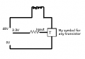
I'm working on a pinball machine which needs 48V solenoids.

I cannot get a 4.6 Ohm nor a 11 Ohm solenoid coil for a pinball machine to trigger via any transistors, while operating at 48V. I'm not an electrical guy, my background is in software. I will kindly pay someone a small fee if they can show me an actual physical working circuit.

I've tried TIP120, TIP102, IRF3205, IRL540N. I tried many resistor values which I learned previously I was using too high of resistor values and that fixed some problems. But everyone says use logic level mosfets, not working either. I tried with heatsinks and without, doesn't matter because they burn up so quickly. Can't seem to learn transistor 101 even though I've searched for hours online and had you guys try to help me before.


upload_2019-5-1_20-48-29.png
 

Attachments

wayneh

Joined Sep 9, 2010
17,496
How confident are you about the gate voltage when the solenoids are powered? A sagging voltage could cause incomplete switching of the MOSFET, causing too much resistance for a 10A current load. Let us know where that gate signal is coming from. I’d feel a lot better if it were 5V or more. Maybe you need a small level shift transistor to get that voltage up.

Please also specify what kind of diodes you are using. Maybe they’re not up to it.

I know it’s no consolation but it should work based on what you’ve provided so far. The problem must lay in something not being what we think it is.

The IRL540N data sheet shows an Rds of maybe 0.07 or maybe 0.08 for a 3.3V gate. At 10A, that’s up to 8W which is a lot of heat!
 
Last edited:

Ylli

Joined Nov 13, 2015
1,086
48 volt solenoids with coil resistances of 4.6 and/or 11 ohms!! Are they lifting the whole pinball machine?

Are you sure these solenoids are rated for 48 vDC and not 48 vAC? If they are designed for AC, their inductance will limit the current, but switching with a transistor will be a bit more complicated.
 

Dodgydave

Joined Jun 22, 2012
11,284
Usually pinball solenoids are AC fed with push buttons when i worked on them in the 80s, check the voltage that feeds these solenoids first, or post pictures of the inside....
 
"48 volt solenoids with coil resistances of 4.6 and/or 11 ohms!! Are they lifting the whole pinball machine?" Yes. I might go to a local machine to check out a modern stern machine. They are running definitely running 48V per their datasheets and they list the coils as 26gauge, 800 to 1200 turns (11ohms or so). You do need that kind of power to really kick a pinball around. Modern pinball machines are fast.

"Usually pinball solenoids are AC fed with push buttons when i worked on them in the 80s"
Yes, however modern machines are transistor controlled, which means they have a diode across the coil to prevent voltage spikes backwards, which means AC is definitely not in modern, otherwise youd have a short circuit across the coil leads since the diodes are soldered to both coil leads. AC would make it completely skip the coil when voltage is reversed.

"I’d feel a lot better if it were 5V or more."
I did try a direct 5.2V with no resistor to the gate. I manually connected that to positive and back to ground to make sure it turned off the transistor. With the 11.5ohm
I've tried so many variables at this point, I'll have to go back to the 11.5Ohm strictly.

As for wattage most of my tests were with the 11.5Ohm, which is 4.1Amps, but in actual reading its a little less, like 3.8, so power in the mosfet would be (3.8*3.8)*.07 = 1.0108 Watts.
 

DickCappels

Joined Aug 21, 2008
10,153
That calculation is only correct if the MOSFET is fully on.

Have you looked at existing driver circuits for your chosen solenoid? If you can copy one of them and make it work you will be on your way.
 

djsfantasi

Joined Apr 11, 2010
9,156
Someone help me here. I was trying to switch a high power FET (12V) with 5V from a microprocessor. Someone explained to me that I needed to switch the power MOSFET with a higher gate voltage.

I ended up driving the gate of a P-channel MOSFET with a pull up resistor from the gate to the higher voltage and a second logic level N-channel MOSFET between the gate to ground.

I don’t know if this will help. I hope that “someone” sees this and responds.

My second thought is that you might need more than a diode to absorb the back EMF from the cool.
 

wayneh

Joined Sep 9, 2010
17,496
Someone help me here. I was trying to switch a high power FET (12V) with 5V from a microprocessor. Someone explained to me that I needed to switch the power MOSFET with a higher gate voltage.
That would be very true if you were using a normal MOSFET. Five volts won't do it. But for the IRL540N example here, 5V "should" be fine. Even the TS's 3.3V should work although he might need a heat sink.
I ended up driving the gate of a P-channel MOSFET with a pull up resistor from the gate to the higher voltage and a second logic level N-channel MOSFET between the gate to ground.
Some sort of driver like this might help the TS
My second thought is that you might need more than a diode to absorb the back EMF from the cool.
That's in the area of what I'm thinking - that the problem is something being assumed or overlooked. Gate voltage sags, diode not big enough, something like that.
 

ScottWang

Joined Aug 23, 2012
7,397
IRF3205, IRL540N Please see the page 2 to check the Rds(on) an Vgs.
IRL540N -- When Rds is on, Vgs=10V, so this component doesn't match what your Vgs=3.3V needed.

IRF3205 -- When Rds is on, Vgs=4V, so this component a little matched what your Vgs=3.3V needed, but you need to find an Ids with 3 times of the I_load.

The better is to find the Vgs<=2.5V when Rds=on and the Ids with 3 times of the I_load, Rds(on)<5mΩ.
 

BobTPH

Joined Jun 5, 2013
8,806
Looking atvthe dataheet for IRL530, with a gate voltage of 3V and current of 10A, the Vds is 0.8V. That is 8W of dissapation. Are you using a karge enough heat sink for that power level?

Get a better MOSFET. You can find MOSFETs with Rdson less than 10mV.

Bob
 

ronv

Joined Nov 12, 2008
3,770
This may be a dumb question.
Are they AC or DC solenoids?
My guess is they are AC thus the DC circuits don't work so good.
 

Thread Starter

adam450

Joined Mar 19, 2019
34
Well I solved my problems. From my previous thread I was upping base resistor thinking I could weaken coils that way but that was a beginner issue. Then I made my own coils with multiple leads so I could test the coils with different amounts of turns, however there was a lead touching the actual diode, so it short circuited and bypassed the entire coil. After realizing this, I fixed the short, and then realized due to me stepping on my coil or some other thing, the coil was reading no resistance, so I broke the coil.

After this I went back to the higher power solenoid and it would burn out. I came to the idea of trying to power the coil with multiple transistors and that worked great. So I'm good to go finally.


Yes, pinball coils do need crazy power to kick the ball. https://www.flippers.com/coil-resistance.html You can go to this link and search "23-800". That's a standard flipper coil. 23 gauge, 800 turns, 4.5 Ohm. Modern games run 48V (you can read pinball specs on manufacturer websites). That would be 10.6 Amps, however my actual reading (which is probably from some heat increasing resistance slightly), is usually about 90% of the calculated current.
 

wayneh

Joined Sep 9, 2010
17,496
I came to the idea of trying to power the coil with multiple transistors and that worked great. So I'm good to go finally.
I'm glad you're back in business but I have no idea what you mean by this. I think some here like me would be curious to see what your solution is.
 

Thread Starter

adam450

Joined Mar 19, 2019
34
"I think some here like me would be curious to see what your solution is." I have two transistors in parallel so that as current flows out of the coil, it splits to two transistors so they share the current flow to ground.
 
Top