High Speed data aquisition design

Deleted member 115935

Joined Dec 31, 1969
0
Ok, Those Photo multiplier diodes,
have a rise / fall time sub 1 ns.
so if you sample every 100ns, you are going to miss the edge,
and depending upon your input pules width, the pulse.

You need to first look at the rising / falling edge speed,
this defines the bandwidth of the front end you need,

with the max 1ns rise time you have, you will need a maximum sample time of an ADC of 0.5ns ( 2 GS/s )
to measure accurately and allow a reasonable low pass anti alias filter at the front end,
your probably going to sample at 5 Gs/s

That's a thousand dollar ADC, that needs some nice care an attention. Not compatible with an Arduino, you need an FPGA to capture and sort that data rate.

Take step back,
why do you need to measure the amplitude at a constant rate ?
Are receiving a fairly infrequent pulse,

A thought, might to be to use a track hold circuit, driven by an amplitude comparator ?
the output will then be a DC voltage, till the next sample is taken, which can be read by a much slower ADC.

How often are the pulses ?

If all you want is time,
use a time to digits convertor

https://www.ti.com/lit/gpn/tdc7200


One other note. Those things are very sensitive, ESD, EMI are all big problems, as is the bias constraints, Very easy to blow.
ensure you have read and understand the tons of app notes that On semi have on these devices,
as well as the models they have for simulation.
 

Thread Starter

pyroartist

Joined Oct 9, 2015
131
Thanks for studying the details on the SiPM device. I am not following your logic about looking for an "edge" and don't see the need for anything greater than half my signal width so a 20 MSPS A/D should work just fine. I only need to measure the signal sometime during the middle of each 100 ns. window so no need for ultra fast A/D. My biggest concern with the suitability of the SiPM is the 73 ns recharge time. Because I want to sample the returning signal every 100 ns and this is a bit close to the recharge time. What do you think about that? So maybe sample at ~85 ns in.
I thought that most modern A/Ds have built-in track and hold circuits.
ESD is not a big problem if you are careful and these devices are not affected by EMI or magnetic fields. The bias is one of the nicest features! Older versions of Geiger mode avalanche photo diodes required 200 to 400V to obtain breakover. I guess technology marches on because these only need 30 to 35 Volts. (a 5V range, so not critical!)
 

Thread Starter

pyroartist

Joined Oct 9, 2015
131
I am sending out a 100 ns pulse and looking at the "echo" over the next 2us. Then there is plenty of microseconds for cool-down of the laser diode (it has a .05% duty cycle) and processing before the process is repeated 1000 times (1 second) after which the data in each range bin is totaled, scaled and displayed.
You were looking in the datasheet at the diagram of response in ONE micro-cell. Don't forget that the chip contains 620 microcells and their outputs are all in parallel to the one output pin! This means that as an individual photon fires a cell, other cells nearby will be firing and recovering because they are being struck by different photons. Probably the best picture you can look at is the dark current diagram to see what the output will be when receiving signal, except amplitudes will be higher due to more photons striking cells. I saw a good diagram showing this a few days ago but can't find it right now. Similar graphs are shown in this massive collection: https://www.google.com/search?newwi...3LjAuMZgBAKABAaoBC2d3cy13aXotaW1n&sclient=img

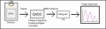
If the recharge time is a problem I can widen my receive window to 200 ns with little difference in results. Also found this one diagram that shows a charge-integrating A/D being used to read the SiPM. Are you familiar with those?
 

Attachments

Deleted member 115935

Joined Dec 31, 1969
0
I am sending out a 100 ns pulse and looking at the "echo" over the next 2us. Then there is plenty of microseconds for cool-down of the laser diode (it has a .05% duty cycle) and processing before the process is repeated 1000 times (1 second) after which the data in each range bin is totaled, scaled and displayed.
You were looking in the datasheet at the diagram of response in ONE micro-cell. Don't forget that the chip contains 620 microcells and their outputs are all in parallel to the one output pin! This means that as an individual photon fires a cell, other cells nearby will be firing and recovering because they are being struck by different photons. Probably the best picture you can look at is the dark current diagram to see what the output will be when receiving signal, except amplitudes will be higher due to more photons striking cells. I saw a good diagram showing this a few days ago but can't find it right now. Similar graphs are shown in this massive collection: https://www.google.com/search?newwi...3LjAuMZgBAKABAaoBC2d3cy13aXotaW1n&sclient=img

If the recharge time is a problem I can widen my receive window to 200 ns with little difference in results. Also found this one diagram that shows a charge-integrating A/D being used to read the SiPM. Are you familiar with those?

A 100ns pulse,

Quiet big, OK, sorry, I'm more used to looking at ns pulses with those things,
Do you need such an expensive device ? how may photons are you expecting ?

100 ns
if its a pulse, you want to be able to sample the top of the pulse,
to find this reliably , you need to sample more than once per 100 ns
As the pulse is not repeatable, each is different, Nyquist is not so relevant , its sampling theory ,

To be able to characterise a 100 ns pulse, you need to get at least 4 samples
As an example, a scope, for a none repetitive pules, you would be looking to a sampling ratio of 10 times,

so for a 100 ns ( 10MHz ) pulse, you need a sample rate of at least 40 Ms/s,

Next up, the bandwidth of the front end electronics.
You want to protect the rising / falling edges, and not have ringing , under / over shoot.
else your not measuring the pulse, but your front end.

If your front end for instance has a bandwidth of 5 MHz, then you are limiting the rise / full times of your pulse,
it might not get to the full level you expect. ( under / over shoot )

I'd be looking at a standard 125 MHz ADC system in your case,
feed into a FPGA to extract the data ,

look here at the sort of system your looking for

https://www.ti.com/tool/TIDA-01187?...KWjiBZ-rFHYPNXLKjEAaAlb-EALw_wcB&gclsrc=aw.ds
 
Top