High pass 3° Order filter

Thread Starter

sohardtoexplain12

Joined Sep 8, 2026
4
Hello all,im new here.
I was trying to do calculation for a high pass filter and i found online that they do basically this, they select butterworth values as: g1=1, g2=2 and g3=1, at this point, my impedance line is r0=50ohm, and the frequency cut off value i chose to be 800MHz (L5 band is at 1176MHz)


  1. Immagine


    i was trying to do calculation and i found online that they do basically this, they select butterworth values as: g1=1, g2=2 and g3=1, at this point, my impedance line is r0=50ohm, and the frequency cut off value i chose to be 800MHz (L5 band is at 1176MHz) The calculations i did are these: C1=1/G1R02pif=3.98pF L2=R0/G22pi*f=4,97nH C2 same as C1, these values i found to be the same on a CLC filter calculator.
    I didnt stick to a book tho, should i look for an example from a book or maybe put the values in a simulation tool till i find the frequency response i need?

    The screenshot is taken from this IC: B39162B8389P810, which i selected as pass band for my GPS module, which works at L1/L5 frequencies.

    Thanks for all the help!
 

0ri0n

Joined Jan 7, 2025
190
The datasheet suggests a termination of 50 Ohm || 5nH for the SAW filter. Being a dual bandpass (L1 + L5) filter it is unclear to me if this termination is valid for both bands. Consider a L-C-L highpass filter where you can merge one of the inductors with the 5nH needed for matching. Finally convert the inductors to short, high impedance transmission lines.
 

Thread Starter

sohardtoexplain12

Joined Sep 8, 2026
4
The datasheet suggests a termination of 50 Ohm || 5nH for the SAW filter. Being a dual bandpass (L1 + L5) filter it is unclear to me if this termination is valid for both bands. Consider a L-C-L highpass filter where you can merge one of the inductors with the 5nH needed for matching. Finally convert the inductors to short, high impedance transmission lines.
So to make the correction of the matching here i need and inductor of 5.1nH?

I have calculated 5nH around, i can put 5.1nH It wont make much difference no?


Thanks!
 

Thread Starter

sohardtoexplain12

Joined Sep 8, 2026
4
The datasheet suggests a termination of 50 Ohm || 5nH for the SAW filter. Being a dual bandpass (L1 + L5) filter it is unclear to me if this termination is valid for both bands. Consider a L-C-L highpass filter where you can merge one of the inductors with the 5nH needed for matching. Finally convert the inductors to short, high impedance transmission lines.
I cant do the merge, i would need a frequency of over 1.56GHz in order to use a single inductor, i cant keep with the CLC type?
 
So to make the correction of the matching here i need and inductor of 5.1nH?
Yes, according to the datasheet the filter needs a matching network in the form of a 5.1 nH inductor to ground at input and output. These small shunt inductors can also be done in distributed form as a transmission line.

I have calculated 5nH around, i can put 5.1nH It wont make much difference no?
It's 5.1 nH not 5nH as I wrote.

I cant do the merge, i would need a frequency of over 1.56GHz in order to use a single inductor, i cant keep with the CLC type?
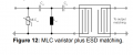
The type of filter for ESD protection is up to you. Either a 3rd order C-L-C (e.g. 4.7 pF - 7.5 nH - 4.7 pF) or L-C-L (e.g. 13.7 nH - 3.3 pF - 13.7 nH) highpass filter. The L-C-L filter provides basic ESD protection due to having a DC path to ground at both ports. For improved protection place a bidirectional suppressor diode (e.g. a ultra-low capacitance ESD8011 or similar) in front of the filter, close to the antenna port.
 

MisterBill2

Joined Jan 23, 2018
28,169
Certainly the accurate design of filters with adequate performance is not "simple!" In addition, the actual creation of a filter based on calculated values has been a big challenge for me. Getting the required performance based on the calculated values has never been simple.
 
Top