Hi. New here. Car battery reads 11.78V

Thread Starter

B-JoJo-S

Joined Jan 3, 2026
475
Just came across this video:
Didn't realize how easily it would be to change the voltage output of the alternator. Scroll to about 8:50 to see how the guy tricked his alternator into putting out a higher charge.
There's this module you can buy and plug in.
https://voltageboosterpro.com/
This commercially available device has a high/low switch. So you can increase the output (just guessing here) by one diode forward voltage drop or by two, depending on the switch setting. While the commercially available part is half as much as the battery, adding an in-line fuse and diode should drop the sense voltage by 0.6 (guessing) and boost the normal 13.8V to 14.4V. Should be easy enough to come up with my own rig as a plug-in module. Forget the switch.
Two diodes would conceivably go from 13.8v to 15V.

And I still owe you a report on the resting voltage, haven't forgotten.

Editing: Voltage readings are as follows: Wife's Venza reads 12.41V, Rav 4 reads 12.6V but it was driven a few hours ago. OK, so I'm either going to build my own or buy. But I'm leaning away from buying a couple diodes, a switch, a fuse holder and a PCB. Done!
 
Last edited:

MisterBill2

Joined Jan 23, 2018
28,070
Installing and permanently connecting a suitable battery charger is not a big deal at all. The charger can be located in any suitably protected area of the vehicle, and only needs a connection to the battery positive and negative.If the vehicle has one side of the battery tied to the body metal , then only one wire is required.
 
@Prariemystic: Certainly there are both incorrect theories and total lies spewing out over the internet. Consider that assertion about the key fobs to be simply A BIG LIE! All sorts of stuff gets made up, by those with nothing better to do.[...]
What makes you say it's a big lie?

High parasite drain due to the BCM not going into sleep mode, is a huge problem- a basic nightmare for people to troubleshoot.
My comment on the keyfob from an EE that measured parasite drain when troubleshooting his car battery going weak. He parks right next to his house and the keys are on a rack on the inside wall, so the car sees the keyfob nearby constantly.
Others say it takes 30 minutes for it to go to sleep which I doubt he waited for before his measurements.
Others say you first need the door lock/unlock button pressed to cause the BCM wake up/sleep.
 
Where are you getting this information?o_O
Sorry to answer this late, was not feeling smart lol.
Alternators caused problems with idle speed stability and emissions due to random loads getting turned on. It is unexpected load demand when you turn on headlights, rear defog, A/C etc. Alternator IC's did fancy "load response control" (LRC) and thus gradually ramped up load to prevent a stall or emissions surge, giving time for the ECU to compensate.
Then the change is to smart alternators with serial comms to the ECU.

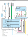
Always check your car's wiring diagram for surprises. This RAV wiring shows the ECU comms with the alternator.
Denso changed from pin 1 being "S" analog voltage sense wire, replaced by "RLO" which is ECU control.
Not sure about Denso but North American brands are using a one-wire LINbus.
You can also peruse alternator regulator IC datasheets to see how complicated they have become.

RAVcharging.png
 

MisterBill2

Joined Jan 23, 2018
28,070
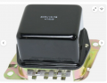
Here is a different bit of information:For many years ALL of the Chrysler vehicles with alternators used a separate regulator that took the "sense" input from a location separated from the alternator by a fair amount of wire harness. The result was both effective in better controlling the battery charge AND handling other large loads, primarily the AC blower motor current, but also the headlights.
Those regulators are simple to trick into providing a higher alternator output voltage, simply by putting a voltage drop into the sense line.
 

Thread Starter

B-JoJo-S

Joined Jan 3, 2026
475
Those regulators are simple to trick into providing a higher alternator output voltage, simply by putting a voltage drop into the sense line.
Exactly the plan for my wife's car. However, the Rav4 ECU directly controls the alternator sense voltage. Which means in order to up the voltage I have to have the ECU flashed. There are a few other things I might have flashed as well. The gas pedal is slow to respond. I could buy a "Pedal Commander", but if I'm on the computer then I might as well have the slow response programmed out. It is actually programmed in that way to enhance the gas mileage by electronically keeping the driver's foot out of it. Personally I like an engine that responds when I step on the gas without having to resort to any tricks like manually downshifting. But that's not the subject. Higher voltage - that's the goal.
 

MisterBill2

Joined Jan 23, 2018
28,070
@ B-JoJo-S
Fortunately you are not the one wanting to get more voltage out of the alternator, up to 24 volts. I have had a regulator fail, $18 for a replacement that took just five minutes to replace. If yours fails, the Rav4 ECU will probably cost a whole lot more, with nothing else failed. THAT is why I like separate modules for each function. MUCH cheaper to replace, and probably more reliable, anyway.
 

Thread Starter

B-JoJo-S

Joined Jan 3, 2026
475
Yeah, I remember the days of the regulator that was bolted to the tire-well on my Ford Granada. Also had a starter solenoid next to it. But back then you could just swap things out. Messing with jetting on carburetors, changing intake manifolds, headers, all that stuff was much easier.
But flashing an ECM to up the voltage doesn't seem like any danger to the entire system. It's a computer, designed to perform as programmed. Changing the programming isn't like changing an alternator belt. Plug in - reflash - done.

Screenshot 2026-01-14 at 8.25.17 AM.png
 

MisterBill2

Joined Jan 23, 2018
28,070
The reason given in post#51 is exactly why I suggested in that other thread about tricking the controller by adding a diode drop in the sense wire connection.
But for the TS question, I have a much different suggestion, based on my experience. That suggestion is to verify the integrity of every bolted connection in the battery charging circuit, which is the circuit from the alternator output to the battery positive terminal. AND also verify the connections between the alternator negative and the battery negative. The first step can be measuring directly between the alternator output connections and the actual battery terminal with the engine running at idle speed.

With some engines in some cars that will require attaching the meter connections with the engine NOT RUNNING, because of the very difficult effort to attach them. This is usually the case on front wheel drive vehicles .
 

Thread Starter

B-JoJo-S

Joined Jan 3, 2026
475
But for the TS question, I have a much different suggestion, based on my experience. That suggestion is to verify the integrity of every bolted connection in the battery charging circuit, which is the circuit from the alternator output to the battery positive terminal. AND also verify the connections between the alternator negative and the battery negative. The first step can be measuring directly between the alternator output connections and the actual battery terminal with the engine running at idle speed.
Why? There has been no indication of any issues. Alternator output was 13.8V. All lights were bright. Horns are loud. Window defrosters run fast and strong. Heated seats can roast my buns. There's no indication of a bad ground. I fully understand the potential issues for bad grounds but we're talking about an AGM battery who needs 14.2 to 14.4 volts to properly charge. I'm learning these things as I go, but I'm learning them.

I'm in talks with a company that can flash my computer and up the alternator voltage to 14.2V. They're talking $350 to $500 (US). So I'm leaning heavily away from that solution. The next considered approach is to put a diode in the alternator sense line. Since I can't do it at the fuse I'd have to dig into the engine compartment to modify the wiring. There's a chance, but I have to do further research to see if I can put the diode in by the computer. Easier to reach and protected from high heat and wet conditions.

Truth is - I'm still working on coming up with an easily implemented solution to my desire.

As this thread opens with "Car battery reads 11.78V" that was a resting voltage. The car had been sitting over night and the voltage was checked in the morning, before starting and running the vehicle. Which is why I asked if I should be replacing an old battery. Nobody advised putting an AGM battery in there and I didn't know enough about AGM's before putting one in. Now I can replace the battery with a wet cell battery, kind of a step back. But now I'd have a brand new battery that I can't do anything with except keep it charged and on a shelf till my wife's car needs a new battery in some years to come.
 

MisterBill2

Joined Jan 23, 2018
28,070
One more possible consideration: Check the accuracy of the meter/probes combination. AND, based on me having no idea as to your equipment or techniques), check the integrity of the connection between your measuring points and the battery terminals.
ALSO, the diode in the sense line concept was what I suggested in another thread for one who was using a separate engine driven alternator to power agricultural hand tools. Probably it does not relate well to your automotive application.

AND, one more idea is to put a "trickle charger" on your battery for a few hours, then disconnect it and check the battery voltage. IF it comes up to a better voltage, over 12 volts, then suspect your charging system. I did have a single-failed-diode problem a few years back, and the result was a constantly undercharged battery. It never went dead, but it never reached the right voltage.
 

Thread Starter

B-JoJo-S

Joined Jan 3, 2026
475
Mister Bill: There has been no problems with the charging circuit or battery connections. This has been verified. The ONLY thing I'm after is modifying the output of the alternator to suit the needs of an AGM battery.
 

MisterBill2

Joined Jan 23, 2018
28,070
OK, and sorry if I got things confused. another current thread has a n issue for one who was using a separate engine driven alternator to power agricultural hand tools. Probably it does not relate well to your automotive application. For that one I suggested the series diodes in the sense line if the original regulator.
 

Thread Starter

B-JoJo-S

Joined Jan 3, 2026
475
OK, and sorry if I got things confused. another current thread has a n issue for one who was using a separate engine driven alternator to power agricultural hand tools. Probably it does not relate well to your automotive application. For that one I suggested the series diodes in the sense line if the original regulator.
Makes good sense. I never thought of that before researching this subject.
 

MisterBill2

Joined Jan 23, 2018
28,070
As a diagnostic test, one option would be to disconnect the charger and charge the battery with a different charger that you have verified delivers at least 14 volts. charge your battery for at least two hours, then disconnect the charger and measure the voltage..

BUT for charging an AGM battery to a different voltage, adding one or more voltage drops to the regulator sense line is the cheapest and simplest, easily reversible way to go.
 
Toyota is a bit strange (cheap?) grounding the battery with the cable going to the chassis, near the fender.
I'm not sure what ends up conducting the high currents (starting, charging) then to the... engine block where the party is.
Old cars ground the battery to the engine block, with a smaller ground wire to the body. A few car makers uses braided ground straps from the motor to the chassis. But all this costs money for copper lol.
Reading a low charging system voltage, I would measure the alternator's actual output (output bolt and the block) to make sure there is no bad connection, as wll as the voltage difference from the block and battery(-).

VW/Audi have OBD2 configuration for setting the battery size Ah and type i.e. AGM.

Here is a different bit of information:For many years ALL of the Chrysler vehicles with alternators used a separate regulator that took the "sense" input from a location separated from the alternator by a fair amount of wire harness. The result was both effective in better controlling the battery charge AND handling other large loads, primarily the AC blower motor current, but also the headlights.
Those regulators are simple to trick into providing a higher alternator output voltage, simply by putting a voltage drop into the sense line.
Did you mean Delco Remy?
Old Chrysler regulators are a two pin module, FIELD and IGN with no extra SENSE wire that I can see. (I also couldn't see a CHG lamp pin. It's been a while since I was in a Charger or Demon but they must have relied on the volt/ammeter on the dashboard for drivers to spot trouble).
The old Delco Remy (10Si) have a separate sense wire to the battery.

Some IC regulators have an extra resistor to keep them from overvolting if the SENSE wire goes open circuit. This might get in the way of OP's plan.
 
Top