If I hook up a DC to DC converter 12V to 1.4V with a load of 2A to the circuit shown, how long converter will operate if it turns off when the supply drops below 4V? please help me out
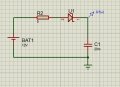
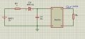
If I hook up a DC to DC converter 12V to 1.4V with a load of 2A to the circuit shown, how long converter will operate if it turns off when the supply drops below 4V? please help me out View attachment 307834
Yes this circuit powers up the converter via U1(+) terminal I am not given any information what converter that is only that it is a step down with a load of 2A
Your circuit does not convert 12V to 1.4V. Instead its output voltage is determined by the load current.
The polarity of the zener diode is backwards so its forward voltage is about 1V when 2A is flowing through it.
Your circuit does not convert 12V to 1.4V. Instead its output voltage is determined by the load current.
The polarity of the zener diode is backwards so its forward voltage is about 1V when 2A is flowing through it.
i am not saying the circuit is the converter what i am saying is if you were to connect a converter between U1 and gnd. I am aware of the V drop across the diode and simple RC network what I can not grasp is this converter (not shown on the pic).and behaviour of the circuit when power is diconnected. Should I just look at the diode just from the perspective of a v drop across it and the discharge of the cap. That's what I was thinking but I am not sure hence the question here.
i am not saying the circuit is the converter what i am saying is if you were to connect a converter between U1 and gnd. I am aware of the V drop across the diode and simple RC network what I can not grasp is this converter (not shown on the pic).and behaviour of the circuit when power is diconnected. Should I just look at the diode just from the perspective of a v drop across it and the discharge of the cap. That's what I was thinking but I am not sure hence the question here.
this is how I think about it and I would appreciate if somebody could correct me if I am wrong. The cap is just a smooting capacitor hence if the converter is drawing 2A at 1v4 from simple ohms law get the power assuming the converter is 100% efficient(ideal) Pin=Pout therefore Iin=2.8/12 and that is the current from the cap at full load power goes off load still pulling with the same current.
That is my straggle I have only a theoretical explanation of the hook up. Further to my previous simplistic explanation I want to add that if you were to treat the converter as a simple buck converter one could think of the timing ( switching frequency) Vout/Vin -duty cycle. since there is a diode lets assume 1Vf of the diode 1v4/11=0.13 and 1v4/4=0.35 for the two extremes of the rails (A,B). If the converter does not sense the power loss the controller will try to adjust the duty cycle of PWM controlling mosfets to make up for the change. Therefore one could express the time it takes for the converter to stay operational (after the power goes off) as a difference in the duty cycle of PWM. Am I on the right track or I missing something important?
What is the purpose of the resistor, diode and capacitor? All it does is waste power. If you want to disable the the converter when its supply voltage is less than 4V, then use a reference and a comparator to do so.
What is the purpose of the resistor, diode and capacitor? All it does is waste power. If you want to disable the the converter when its supply voltage is less than 4V, then use a reference and a comparator to do so.
It is not about controlling the disconnection threshold of the converter. My question is when the power goes off (remove the source battery) how long the converter will operate for?
It is not about controlling the disconnection threshold of the converter. My question is when the power goes off (remove the source battery) how long the converter will operate for?
There's no way to know, because it will be determined by the design of the DC-DC converter. It may have circuitry that disconnects the output if the input voltage drops below a certain level. It has internal capacitors at the input and output whose sizes are unknown.
Thank you for your help that basically means that the circuit and the question associated with it is just a test how deep one can be confused and if it can be. This is something I have received as a test question for a job. Started digging too deep into the converter side I guess I am one of those that can in fact be confused easily. Thanks guys

 Facebook
 Google
 GitHub
 Linkedin