Help with the designing transistor as a switch (saturation region)

Thread Starter

micktosin

Joined Mar 20, 2012
19
Hi there
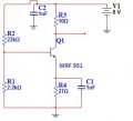
I'm trying to findout how the resistor values of transistor shown below was calculated. From my understanding, this circuit was designed to bias the transistor into saturation region and that's all i know about it. Please how do i go about this, as i need this understanding to design other non linear Circuit?


Thanks in advance.
 

Attachments

debjit625

Joined Apr 17, 2010
790
You have to tell us everything thing about this circuit, as it doesn’t make much sense to me .Using voltage divider at base their will be approx 0.7 volts which is not sufficient for the Vb (voltage at the base) as normally a silicon transistor’s base-emitter junction (Vbe) in forward bias drops approx 0.7 volts and Vb is about Vbe + Vre i.e.. voltage drop across emitter resistor. So Vre will be very small and if Vre is small the current through it will be also very small i.e.. the emitter current (Ie) now we know Ie = Ib + Ic ,so a very small Ib will be not sufficient to drive the transistor into saturation mode. So no way its going to be saturated.

The C1 is a bypass capacitor normally used in AC amplifiers , and C2 is filtering capacitor with a very small value that I don’t understand why? Sometimes we use these to eliminate noise from supply line and place the capacitor very close to the component.

Anyway without details of your circuit I can’t say much…

Good Luck
 

Thread Starter

micktosin

Joined Mar 20, 2012
19
I'm sorry for not providing enough information. This circuit was used as a part of frequency multipliers chain for Transmiter, of which tuned filter was used to select the harmonic.
However, after getting it to work, i couldn't understand how this Voltage divider was calculated base on the Transistor Specifications.
My question is, what step do you think were taken in designing this Circuit to give a value of the resistor shown above?

P.s. I know how to design Voltage divider in the linear region, but not in the saturation region this circuit was designed for.

Thanks.
 

Thread Starter

micktosin

Joined Mar 20, 2012
19
Hello,

In case of a transistor frequency multiplier, the transistor can be biased as an almost class C amplifier.
You might also have noticed that C17 and C21 are grounding the signals for RF.
Bertus
Thank you for the help . But i'm not sure how this method can be use to bias it? Please can you elaborate more on this method?
 
Top