Facebook
 Google
 GitHub
 Linkedin
HI everyone, first time posting here. Thank you in advance for looking and potentially helping out.
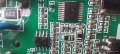
In my infinite wisdom I managed to short the motor control board on my treadmill (an allen key that I was using to tight the front roller, touched the ground terminal of a capacitor on the motor control side -- that I should have been a lot more careful is an understatement). The capacitor's wire got fried. In the process a zener protecting the gate of the main MOSFET and its trace to ground died too. The board is a Digital concepts mec8t. The good news is that the part of the board that was affected by the short was isolated from the rest of the electronics. The control panel works and generates the PWM signal, reads the speed sensor (magnetic) and controls the incline motor just fine. It is the main motor that does not starts. A photo of the board is below. When powered up, the AC LED and 18V LEDs go on. I replaced:
* the MOSFET
* the two triacs (one large connected to motor) and a smaller one that controls the MOSFET somehow.
* the large diode across the motor I tested with a multimeter off-circuit and is fine.
* All electrolytic capacitors
* all SMD transistors and SMD diodes.
* the MPSA43 transistor (seems to be part of a stage that looks at the current being drawn feeding into an opto-triac).
* all opto-isolators (1 for the PWM coming in, 2 forming a feedback loop somehow to the digital controller side -- I think it had an A/D converter to measure motor operation) and opto-triac on the AC side.
I measured all resistors and removed and tested some of the SMD capacitors too. For the resistors, I used my multimeter and tested that the resistance is at most what's marked. I took 2-3 off the board when the resistance was way low and tested them off-circuit -- they measured fine. Not sure this is enough testing for resistors. For capacitors, I tested for shorted ones, some I removed and tested with an LCR meter (not that I know how to use it well). I replaced one or two whose readings were fluctuating. There are few discrete diodes, which I tested with a multimeter and seem fine.
At this point I am a complete loss on what I should try next. One sane option would be to get a replacement board. Unfortunately, I cannot find one The motor is a 130v one. The zener that blew had a z15 marking, and given the operating range of the MOSFET (IRFP250) I replaced it with a 15v one (the red wire connects one side to ground as the trace blew off). The board has 3xLM339 and one LM324 (bottom left on the photo). When I test it with just the 18v power supply, the current limit LED goes on for less than a second, and then goes off. The MOTOR led is faintly lit. I tested the PWM pass through one of the optoisolators (mid-left on the photo) and I can see it coming into the motor control side.
I could try to draw a schematic from parts of interest.
On the photo below, the left side including the transformer works fine. It is the right side that has the problem. On the photo, the resistor next to the MOSFET (220) looks a bit burned off (this was done when testing when the zener got disconnected momentarily -- I tested the resistor out of the circuit and as far as I can tell with my multimeter it is fine).
Any help on what I should be looking at would be greatly appreciated. I have not been able to find any info on this board online and my understanding of analog electronics is very rudimentary.
Thanks!
In my infinite wisdom I managed to short the motor control board on my treadmill (an allen key that I was using to tight the front roller, touched the ground terminal of a capacitor on the motor control side -- that I should have been a lot more careful is an understatement). The capacitor's wire got fried. In the process a zener protecting the gate of the main MOSFET and its trace to ground died too. The board is a Digital concepts mec8t. The good news is that the part of the board that was affected by the short was isolated from the rest of the electronics. The control panel works and generates the PWM signal, reads the speed sensor (magnetic) and controls the incline motor just fine. It is the main motor that does not starts. A photo of the board is below. When powered up, the AC LED and 18V LEDs go on. I replaced:
* the MOSFET
* the two triacs (one large connected to motor) and a smaller one that controls the MOSFET somehow.
* the large diode across the motor I tested with a multimeter off-circuit and is fine.
* All electrolytic capacitors
* all SMD transistors and SMD diodes.
* the MPSA43 transistor (seems to be part of a stage that looks at the current being drawn feeding into an opto-triac).
* all opto-isolators (1 for the PWM coming in, 2 forming a feedback loop somehow to the digital controller side -- I think it had an A/D converter to measure motor operation) and opto-triac on the AC side.
I measured all resistors and removed and tested some of the SMD capacitors too. For the resistors, I used my multimeter and tested that the resistance is at most what's marked. I took 2-3 off the board when the resistance was way low and tested them off-circuit -- they measured fine. Not sure this is enough testing for resistors. For capacitors, I tested for shorted ones, some I removed and tested with an LCR meter (not that I know how to use it well). I replaced one or two whose readings were fluctuating. There are few discrete diodes, which I tested with a multimeter and seem fine.
At this point I am a complete loss on what I should try next. One sane option would be to get a replacement board. Unfortunately, I cannot find one
The motor is a 130v one. The zener that blew had a z15 marking, and given the operating range of the MOSFET (IRFP250) I replaced it with a 15v one (the red wire connects one side to ground as the trace blew off). The board has 3xLM339 and one LM324 (bottom left on the photo). When I test it with just the 18v power supply, the current limit LED goes on for less than a second, and then goes off. The MOTOR led is faintly lit. I tested the PWM pass through one of the optoisolators (mid-left on the photo) and I can see it coming into the motor control side.I could try to draw a schematic from parts of interest.
On the photo below, the left side including the transformer works fine. It is the right side that has the problem. On the photo, the resistor next to the MOSFET (220) looks a bit burned off (this was done when testing when the zener got disconnected momentarily -- I tested the resistor out of the circuit and as far as I can tell with my multimeter it is fine).
Any help on what I should be looking at would be greatly appreciated. I have not been able to find any info on this board online and my understanding of analog electronics is very rudimentary.
Thanks!
Attachments
-
 564.1 KB Views: 11
 -
 616.2 KB Views: 11
 -
 565.7 KB Views: 8
 -
 350.3 KB Views: 8
 -
 935.8 KB Views: 7