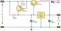
We add Q1 to increase output current capacity of this regulator.
Read this http://forum.allaboutcircuits.com/showthread.php?p=657558#post657558
And Q2 is current limiting for Q1 booster transistor.
Q2 sens the Q1 current via the drop across R2 resistor and cut-off Q1 when voltage drop across R2 resistor is larger then 0.6V.
If the first bit seems a bit too much, then step back a bit (or even to the beginning of Vol 3 altogether).
For this circuit I'll try to explain what the purpose of things are and not the details of how it works at the fine level. Don't worry if this doesn't make a lot of sense until after you've spent some time with the E-book, but be forewarned that the E-book uses predominantly electron flow instead of conventional current flow. Depending on what you are used to, that may make it confusing. I use conventional flow. To minimize the confusion, I'll try to stick mostly to voltages.
As you might already know, the power dissipated in your 7805 regulator is the product of the voltage across it and the current through it. Let's look at what happens as the current needs of the load increase (and we'll ignore the small amount of current that the regulator consumes for its own use).
When the load isn't drawing anything, there is no current being draw by the regulator, so there is no current in the 40Ω resistor, R1, and so the full 12V appears at the input of the regulator and you've got 7V across it. But you have no current through it, so no power dissipation.
As the load starts to draw power, the first (roughly) 15mA flows down through R1 and through the regulator. At this point the regulator is dissipating about 100mW.
As the load draws more power, the voltage across R1 is now enough to start turning Q1 on, which causes current to flow through R2, Q1, and on to the load. Since this current bypasses the regulator, it doesn't cause any further increase in regulator power dissipation. As the current increases, you start developing a drop across R1, but it is small and so you have to get up into the 6A range before it is enough to start turning on Q2. Just before this happens, you'll have about 6A flowing in Q1 and about 30mA flowing through the regulator. The voltage across the regulator will be about 5.8V and it's dissipation will be the better part of 200mW.
As the current demand goes higher, Q2 starts turning on and route the current above 6A down and into the regulator. At this point the regulator current will start going up and the power dissipation will increase in proportion without further limiting other than the built in thermal shutdown protection of the regulator itself.
If I were doing this circuit (and there may be something I'm missing that would make this not a feasible idea) I would have split the 40Ω and put some of it between the input of the 7805 and the collector junction of Q2. This way, as more current was drawn it would cause the voltage to the regulator to fall until it finally drops out of regulation when the voltage across it gets down to about 2V. I think this would require also putting a resistor between the 12V supply and the emitter of Q2. Probably something in the 0.5Ω range. But I need to consider it more before I conclude that this would do what I want, which is to gracefully strangle the regulator to effect a overall current limit.
If I were doing this circuit (and there may be something I'm missing that would make this not a feasible idea) I would have split the 40Ω and put some of it between the input of the 7805 and the collector junction of Q2. This way, as more current was drawn it would cause the voltage to the regulator to fall until it finally drops out of regulation when the voltage across it gets down to about 2V. I think this would require also putting a resistor between the 12V supply and the emitter of Q2. Probably something in the 0.5Ω range. But I need to consider it more before I conclude that this would do what I want, which is to gracefully strangle the regulator to effect a overall current limit.
I think it uses current to strangle the regulator: at about 6A through the top Xsistor, the Vdrop across the 0.1 resistor turns the other transistor on and starts stuffing current into the input of the 7805. This will very quickly cause the 7805 to go into current limiting (at about 1.5A) and it will force the output voltage down and shut the whole thing down.
I think it uses current to strangle the regulator: at about 6A through the top Xsistor, the Vdrop across the 0.1 resistor turns the other transistor on and starts stuffing current into the input of the 7805. This will very quickly cause the 7805 to go into current limiting (at about 1.5A) and it will force the output voltage down and shut the whole thing down.
This just doesn't strike me as good design -- and maybe I'm wrong to feel that way. I just think that the current limiting feature of the regulator, or the thermal shutdown feature, should be seen as a failure mode and should not be relied upon in normal operation. But I can see the argument saying that this is okay to do.
This just doesn't strike me as good design -- and maybe I'm wrong to feel that way. I just think that the current limiting feature of the regulator, or the thermal shutdown feature, should be seen as a failure mode and should not be relied upon in normal operation. But I can see the argument saying that this is okay to do.
I never said it was a good design, I would not put it in anything for my own use. But the 20 years I worked at national Semi, I saw it thousands of times. It's a cheap way to juice up the current and make a 5A regulator. It is super valuable to have the on board current limit/temp limit, you lose that with an external transistor but you save a lot of money.
Micrel made monolithic linear regs that went up to 5A and they cost about $5 each. Linear Technology made 3A/5A regs that were similarly pricey. You could get a 78XX reg for about 20 cents and add a pass transistor and you have the same current capability for under a buck.
In the early 90's we did a cheapo design with a pass transistor for the internal 5V rail for one of Intel's processors using a three terminal reg and a pass transistor. It displaced one of LT's expensive monolithic regulators from the socket and cost them MILLIONS of units sold at about $3.50 each. Our design was under a buck. We had friends at LT at the time who said that loss went all the way up to the CEO.
I don't have a problem with the pass transistor, and this circuit's design for limiting the current is better than not having anything. I would just be happier with a design that limited the current nicely even if I were to put in a regulator IC that had no current limiting or thermal shutdown.

 Facebook
 Google
 GitHub
 Linkedin
 113.2 KB Views: 31





