 Facebook
 Google
 GitHub
 Linkedin
Hi everyone
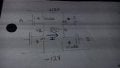
I am trying to understand how to do my assignment, it is a motor that will be controlled with pulse-width modulation and the current is switched by power transistors. The way I think we can do this is with an H bridge by having 4 mosfets, 2 pmos and 2 nmos and having a circuit like the one in the picture.
We need to have a MUX with 2 inputs , A and B that will follow the requirements that when both A and B are ON, the motor will run at 100%, when A is 0 and B is 1 it will run at 30%. One of my problems is that Im not familiar with pulse width modulation, I don't know how to implement it to the MUX.
The power supply +12 volts and -12 volts.
We cannot use any sort of microcontrollers so I think the MUX should be constructed out of discrete components.
My biggest question is how to construct the H bridge such that it is connected to the MUX, how to make them work together
Attachments
-
 45.7 KB Views: 10
Last edited:


