Ah right got myself confused as I was metering in diode mode. Since then I ordered an replacement GBJ2508 hoping I have it by next week. Is there anything else I need to test on the board as I'm beginning to think it could be the micro control chip as I spoken to a repair place they told me it usually the micro control chip that goes faulty on the icon mc2100e rev c. But my question remains how come the console panel get power and functions like there's nothing wrong. Would the micro control chip be responsible for displaying information to the console panel?
As the board is with me and the treadmill is in my friend's house as it abit difficult to do the testing at the moment. I know the dot on the micro control chip is number one which pin numbers do I need to test if there's 5v is present? I have to wait till the gbj2508 is here. As far as I know the led light comes on but stays on also dim looking. Does not blink or flash when the command is pressed from the console panel. I am wondering can I power on the board without the transformer and console panel as there's ac hot usually live (brown wire) and ac net is ground (blue wire) as Im in Ireland
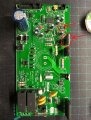
This is the board I have here you might want to zoom in to see which version have
I know there the hd2 that have the signal and voltages changes as I couldn't find the correct info in testing that correctly as it would be helpful to get to the bottem of this issue
There is a reverse engineered schematic that cover most models in some way or another, the micro is pin 10 & 20 for the 5v supply.
To test the board stand alone, you need a 20Hz PWM generator into the HD2 1,2 & 4 pins.
I made some up for the purpose also some avail on ebay.
If 5v is present on the micro is that considering the micro is good or no? What else is left to test? Could it be possible for the hd2 cable going from the board to the console panel broken or the console itself not sending the signal?
If this is the version with the out-board transformer, the board requires this for the LV 15v circuit.
The PWM signal required to test the board comes in onHD2 pin 4 from the console processor.
The only way to get the LED to flash and test the micro is to supply this signal, either from the console or a local test generator.
The DC to the Mosfet does not ramp up until the micro see's this signal
Right I had the gbl2508 installed and same result so for the green wire Im getting constant 3.45v no matter what I press or change the speed it stuck there and for the micro Im getting 5v from pin 10 to 20 but the led stayed dim no flash. I am thinking It might be the console that might be having problems as I don't have the time or patient in fixing it
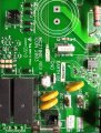
I found one of the cap or resistor as it brown in colour when I was looking for the short on the smd side of things by putting the red probe on the negative A- and I think I found a short on R4 I think next to the R3. Any one know what value is it
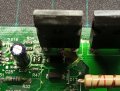
Hi guys! Many years passed, but may be still here I need help with my ICON 2003 MC2100E Rev A - main mosfet (marked Q5 onboard) and mosfet driver (U5) blowup and i cant recognized them. Reading forum i noticed, MC2100 have N-channel mosfet, but my is P-channel Can anybody who have same board take a photo with marks on mosfet and his driver?
Hi guys! Many years passed, but may be still here I need help with my ICON 2003 MC2100E Rev A - main mosfet (marked Q5 onboard) and mosfet driver (U5) blowup and i cant recognized them. Reading forum i noticed, MC2100 have N-channel mosfet, but my is P-channel Can anybody who have same board take a photo with marks on mosfet and his driver?
here is. Looking for PCB i noticed, that this transistor receives + high power, and its output is connected directly to + load (the main motor on the treadmill), accordingly it can be either P Mosfet or IGBT?
 Facebook
 Google
 GitHub
 Linkedin


 I need help with my ICON 2003 MC2100E Rev A - main mosfet (marked Q5 onboard) and mosfet driver (U5) blowup and i cant recognized them. Reading forum i noticed, MC2100 have N-channel mosfet, but my is P-channel