 Facebook
 Google
 GitHub
 Linkedin
Hello ,
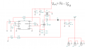
I'm having problem with understanding this circuit
from what I have read in the datasheet , Vo=1.26(1+R1/R2)
http://www.ti.com/lit/ds/symlink/lm3488.pdf
I have a working circuit with
R1= 28K , R2=18K and I'm getting Vo=12V
how could it be?
what am I missing?
this is the circuit -
I'm having problem with understanding this circuit
from what I have read in the datasheet , Vo=1.26(1+R1/R2)
http://www.ti.com/lit/ds/symlink/lm3488.pdf
I have a working circuit with
R1= 28K , R2=18K and I'm getting Vo=12V
how could it be?
what am I missing?
this is the circuit -
Attachments
-
 38.2 KB Views: 71
 The circuits in the data sheet use a simple inductor.


