Help With Kirchhoff's Law!

Thread Starter

FarmerGiles97

Joined Nov 6, 2018
7
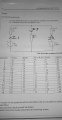
Im tryna do a college assignment, but im finding it hard to understand my teacher, ive spoken to half the class and they are finding it hard to do the assignment too. i am very new to electronics, so if someone could tell me if i am doing this correct, and could help me solve the last part that would be amazing.


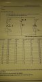
Sorry for the bad hand writing.

https://imgur.com/a/LLXqbZT
 

WBahn

Joined Mar 31, 2012
32,852
You don't define what I1, I2, or I3 are. You need to define not only which branches they are in, but in what direction they are flowing. Don't make us (or the grader) guess.
 

Thread Starter

FarmerGiles97

Joined Nov 6, 2018
7
I dont get what you mean?

Ive showed you the whole qustion of what ive been given. I need to know how to do the last part of the equation.
 

WBahn

Joined Mar 31, 2012
32,852
I dont get what you mean?

Ive showed you the whole qustion of what ive been given. I need to know how to do the last part of the equation.
Your equation uses the variables I1, I2, and I3.

These are NOT defined as part of the given question. YOU have chosen to use them. So YOU need to define them.

For instance, where in that circuit is I3 and in what direction is it flowing?

Without that information specified, your equations are meaningless.

YOU might know what they all are, but WE don't! YOU need to provide that information to whoever it is you want to read and understand your work, which includes the grader.

Don't make us (or the grader) guess or try to back out what your definitions are -- TELL US!

You also should start properly tracking your units throughout your work -- you will see your grades improve significantly if you get in that habit.
 

WBahn

Joined Mar 31, 2012
32,852
Okay, i get you now.

Would this be better?
Yes, that is much better.

The next thing that will help you and those reading your work out is to identify where your equations are coming from. Your first equation is KCL applied at the top node (and this one is quite obvious). But your next equations are KVL equations around different loops and so it would be nice for you to say which loop each equation is for. Otherwise we have to play detective and figure it out. If you really want to be nice (and being nice to graders is very much in YOUR best interest), then also tell them how you are building the equations. For instance, you might say:

KCL at top node: I1 + I2 = I3

KVL loops set sum of voltage gains from sources equal to sum of voltage drops across resistors.

Left loop: 10 V = 19 Ω·I1 + 9 Ω·I3 (CW)
Right loop: 15 V = 14 Ω·I2 + 9 Ω·I3 (CCW)

The next thing you might want to do is check your next steps for silly math errors.
 

WBahn

Joined Mar 31, 2012
32,852
No, you are not right.

Since you don't show hardly any work, in particular where this 0.972 figure comes from, I can't give you much more than that.
 

Thread Starter

FarmerGiles97

Joined Nov 6, 2018
7
10 = 28I1 + 9I2

15 = 9I1 + 16I2


9l2 = 10 - 28I1

9l1 = 15 - 16l2


I2 = 10/9 - 28I1/9

I1 = 15/9 - 16I2/9


Now I substitute I2 in the second equation with the first equation:


I1 = 15/9 - 160/81 + 16*28I1/81 = -25/81 + 448I1/81


From here I can work out the value of I1:


367I1/81 = 25/81

367I1 = 25

I1 = 25/367 ~= 0.07


Using this result I can find the value of I2 as well by using the first equation:


I2 = 10/9 - 28(0.07)/9

I2 = (10 - 28 * 0.07) / 9 ~= 0.9


From here, I3 is just:


I3 = I1 + I2 ~= 0.97

This is how i got my answers?
 

WBahn

Joined Mar 31, 2012
32,852
So let's see if your answers for the current are correct.

You say that I1 = 0.07 and that I2 = 0.9. I'm going to have to assume that you mean 0.07 A and 0.9 A since you won't track your units (and I'm going to stop trying to help you unless you start).

Does this make sense?

Let's round I1 to 0.1 A. That means that the voltage on the top node (based on the left side of the circuit) would be 10 V - 1.9 V or about 8.1 V (it'll actually be higher than this). Meanwhile, the voltage on the top node (based on the right side of the circuit) would be 6 V if R2 were just 10 Ω. With it being 14 Ω it will be considerably less. So, without even pulling out a calculator, we know that those two values for I1 and I2 cannot be correct.

If we do pull out the calculator, we get that the voltage on the top node via the left edge would be

Vtop = 10 V - (0.07 A)·(19 Ω) = 8.67 V

while if we go along the right edge it would be

Vtop = 15 V - (0.9 A)·(14 Ω) = 2.4 V

You need to get in the habit of checking your answers, both the final answers and the intermediate answers. Remember, in the real world there won't be anyone there to ask if you are correct or not -- if there were, they wouldn't need to pay you to solve the problem in the first place. Fortunately, the validity of the answers to most engineering problems can be determined from the answers themselves.

When you DO have someone to check your work, you might consider actually paying attention to what they suggest. After verifying that your initial equations were correct and recommending how better to present them, I said, "The next thing you might want to do is check your next steps for silly math errors."

You responded "Right" and then proceeded to completely ignore that recommendation and charge ahead using a pair of equations, namely

10 = 28I1 + 9I2
15 = 9I1 + 16I2

that you had just been given a HUGE hint were wrong.
 

Thread Starter

FarmerGiles97

Joined Nov 6, 2018
7
You tell me my answer is wrong, but then dont tell me what i have to do to make it right? So how are you helping at all? I went to another forum to get help because honestly, you dont help at all.

Ive checked your profile and all you do is go around on other people needing help and talk down to them, and just tell them theyre wrong.

Some of us have never done electronics before and need some more understanding. Through this forum would be good for help, but there people like you acting like a complete dick.

Ill be going to other forums in the future.
 

WBahn

Joined Mar 31, 2012
32,852
So, you are told to check for silly math errors in going from

I1 + I2 = I3
10 = 19I1 + 9I3
15 = 14I2 + 9I3

to

10 = 28I1 + 9I2
15 = 16I2 + 9I1

and that's not enough for you to even make an attempt to find your mistake?

This has nothing to do with understanding electronics, it has to do with not being able to spot that 9 + 14 is not equal to 16 even when you are directed right to the point where you made the mistake. You know fully well that 9 + 14 is not 16 and you are fully capable of spotting it, you just don't believe that it is your responsibility to do so. It has to do with not caring about learning how to present your work, do your work so that you don't make as many mistakes, or check your own work so that you can catch mistakes that you do make.

BTW, we don't delete accounts and what you post, provided it doesn't violate the rules, remains posted for archival purposes. That's what you agreed to when you joined.

You can either simply not use your account, or if you don't think you will be able to resist the temptation, you can request that we permanently ban your account. Your choice.
 

MrAl

Joined Jun 17, 2014
13,707
Hi,

I had trouble reading the last image posted so here is a better image. Maybe this will help a little anyway.

WBahn: You've got to stop saying, "Yes that's much better", to students as they might get mad at you :) :)
 

Attachments

Did the TS not see the instructions at the end of the assignment:

"results for the tasks should be submitted with all calculations clearly identified.
assumptions made should be stated.
results should be neatly presented and working shown."
 
Top